Content brought to you by Motor Age. To subscribe click here.
What you will learn:
•Variable displacement compressor (VDC) operation
•A/C pressure gauge interpretation
•Proper testing procedures
Ford Motor Company introduced the Variable Displacement Compressor (VDC) during the 2012 model year. The VDC does precisely what the name suggests; it varies the displacement of the compressor to achieve desired suction and discharge pressures. Compressor displacement is determined the same as engine displacement, by counting the cubic centimeters of space in the chamber above the pistons. The VDC uses a swash plate to change displacement by altering the piston stroke length.
Compressor types
The Internally Controlled Variable Displacement Compressor (IVDC) uses an internal pneumatic control valve to control the de-stroking and full-stroking of the compressor. The position of the control valve is determined by suction side pressure.
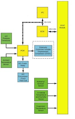
Compressor displacement on the Externally Controlled Variable Displacement Compressor (EVDC) is manipulated by an electric control valve commanded by the Powertrain Control Module (PCM).
The end game in both cases is to prevent evaporator freeze-up and control cabin temperature by regulating suction and discharge pressures. Evaporator freeze-up is inevitable if the A/C compressor is allowed to run continuously, especially if the ambient temperature isn't very high. Ice forming on the evaporator blocks airflow, preventing evaporation (heat exchange). A/C systems with a fixed displacement compressor avert evaporator freeze-up by governing the duty cycle of the A/C clutch. Compressor on-off time is determined by either suction side pressure or evaporator temperature. Here's the get-up and go of an EVDC system. The following conditions typically must be met for the PCM to energize the A/C compressor clutch relay:
• Evaporator temperature is above 32 degrees F
• The PCM does not detect a wide-open throttle event
• Ambient air temperature is above 30.2 degrees F
• A/C discharge pressure as detected by the transducer is within specs
• Climate control settings desire the A/C compressor to run
• Engine coolant temperature is within a normal operating range
Some of these inputs are delivered directly to the PCM, while others originate in different modules and are communicated to the PCM via the network.
VDC compressor system operation
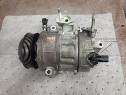
The control valve is located at the rear of the compressor (Figure 1). A pulse width modulated signal from the PCM controls the valve, regulating suction side pressure at the compressor. This variance in pressure adjusts compressor displacement by changing the swashplate angle, achieving a target evaporator core temperature of 37.4 degrees F to 46.4 degrees F.
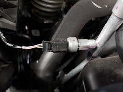
The PCM continuously monitors the A/C Pressure Transducer (ACP) to verify that discharge pressures are within operating range (Figure 2). The PCM will disengage the A/C clutch if a condition causes discharge pressure to go too high. This includes low airflow through the condenser, an engine overheating event, or a system overcharge. The PCM also will not allow the clutch to engage if the ACP reports that system pressure is too low.
The Thermostatic Expansion Valve (TXV) slows down refrigerant flow as it enters the evaporator core and provides the orifice that separates the low and high-pressure sides of the refrigerant cycle. An internal temperature sensing bulb senses the temperature of the refrigerant leaving the evaporator. A pin valve inside the TXV controls refrigerant flow based on evaporator outlet temperature.
Most everything else about VDC operation is comparable to the process of a typical fixed-displacement compressor. The cooling fan increases airflow through the condenser, and the HVAC module controls all the actuators to direct airflow to the proper vents. Most of what you will see on a VDC system is basic, so don't forget your basics when analyzing these systems. It's easy to get caught up in the latest technology while ignoring the basics that brought you here in the first place. Pull DTCs, check refrigerant charge and check for refrigerant leaks. A fried A/C clutch is just that, “a fried A/C clutch.” Whatever cutting-edge operating system you're analyzing, don't forget your basics.
A different approach to analysis
It's most important when analyzing pressures on a VDC system that it's sufficiently charged, and ambient temperature is over 70 degrees F. We used to look at pressures in an A/C system with a fixed displacement compressor and say, "Looks like the charge is a bit low, but the pressures look good." We determined that even though the pressures were low, they were in a good place relative to each other, so the system was operating correctly. We could also compensate for low pressures and a short clutch duty cycle if the ambient temperature was low enough (low heat load on the system). Variable displacement compressors react to these conditions (changing pressures) in a way that could suggest a blockage when no blockage exists. So, if you have any reason to doubt the refrigerant charge is sufficient, recover, evacuate, and recharge before further analysis.
For example, say a 2015 Explorer comes into your shop with a complaint of "A/C blows warm, compressor inoperable," Retrieve and pursue any HVAC-related DTCs in all modules before proceeding with any other diagnostic procedure. This is the case when analyzing any system operated by a module. HVAC-related DTCs can be stored in numerous modules; Body Control Module (BCM), PCM, HVAC, and Front Interface Control Module (FCIM) are just a few. Next, check the refrigerant charge. Static pressure should be no less than 45 psi. If the pressure is below 45 psi, check for leaks, charge the system, and check operation. If the compressor is still inoperable, perform a network test. It's good to verify the integrity of the network right from the start. If there's a network communication issue with the FCIM, BCM, PCM, or HVAC control module, your climate control analysis will morph into network analysis (Figure 3).
Bad inputs equate to bad outputs
If all modules pass the network test and the A/C clutch will not engage, view the ACP PID (ACP_PRESS) in the PCM. The ACP value should be within 15 psi of actual discharge pressure on the manifold gauge. It's not uncommon for the PCM to shut down the A/C clutch due to a faulty ACP reading. An erroneous value from an ACP can also cause the PCM to shut down the A/C clutch intermittently. I serviced a Fusion with an ACP reading 85 psi over actual discharge pressure. The A/C would shut down when the ACP value exceeded the normal range, even though actual discharge pressure was within range.
Monitor the Ambient Air Temperature Sensor (AAT), Evaporator Temperature Sensor, Engine Coolant Temperature Sensor (ECT), and Cylinder Head Temperature Sensor (CHT) (Figure 4 + Figure 5). The A/C clutch will not engage if the evaporator temperature or AAT is too low and if ECT or CHT is too high. If you're analyzing an intermittent issue, it's best to compare more than one temperature sensor's values. A sensor can be inaccurate and still be within range at that time, only to drift out of range when conditions change.
The best time to check the relative values of temperature sensors is after the vehicle has been shut down for a few hours. This way, all the temperature sensors should read about the same. Monitor all the temperature sensors listed above and throw in the Intake Air Temperature Sensor (IAT). We're monitoring the IAT as a reference point; it does not affect climate control. If the vehicle has been shut down long enough, all temperature sensors should show close to the same temperature.
For example, if the evaporator temperature sensor reads 60 degrees F, and all the other sensors are at 70 degrees F, the A/C will work because the evaporator sensor is within range. The problem occurs when the actual evaporator core temperature drops to 40 degrees F, and the sensor reports a value of 30 degrees F, shutting down the A/C. When the vehicle gets to your shop, the evaporator temperature sensor value will return within range. So, if you don't compare it to other sensors, you won't know that it was the cause of the malfunction.
If all these things check out and you still have no A/C clutch operation, pull the A/C clutch relay. From here, you can verify the main power to the relay, power from the PCM power relay, and PCM request signal. You can also jump power directly to the compressor clutch circuit. From this location, you should be able to diagnose a circuit issue, a defective clutch, or a faulty relay. Don't forget about the A/C clutch ground circuit.
A/C system performance testing
If the clutch is engaging and the A/C is still not working correctly, you need to know that the compressor can change displacement. You can verify the compressor is changing displacement by performing a VDC performance test. During the EVDC performance test, you will monitor the amount of current flowing through the compressor control valve circuit and its effect on system pressures.
Be sure that the refrigerant is at the correct capacity and ambient temperature is above 70 degrees F. Remove the fuse in the battery junction box that powers up the control valve and attach your ammeter across both fuse connectors. This will allow you to see when the control valve is energized. Hook up your manifold gauges. Turn on the heat and let it run for about five minutes to warm up the passenger compartment and the climate control housing.
While monitoring the ammeter and the gauges, turn the A/C on, direct the airflow to "panel," and position the air inlet door to "outside air." Initially, you should see the amperage increase to about 1A. This means that the control valve is energized. The clutch will engage, discharge pressure should increase, and suction pressure should decrease, just as it would in any operating A/C system.
After a few minutes, the amperage and the discharge pressures should fall, and the suction pressure should increase. What you're seeing is normal operation. As the evaporator temperature sensor reports a decrease in evaporator temperature, the PCM commands the control valve to de-stroke the compressor. This creates less pull and less push, which is indicated in the pressure readings. If you don't see the initial increase in amperage, the control valve isn't energizing, either because it's not being commanded or it's defective. If the amperage decreases after a few minutes and the pressures don't change, the compressor isn't changing displacement and should be replaced. DTC P06A0 will store in the PCM (most of the time) if there is a problem with the control valve circuits or the control valve itself.
You should expect to see the same results when conducting a performance test on an IVDC compressor (minus the amp reading). The temperature change at the evaporator should lower suction pressures enough to force the compressor to de-stroke, changing the pressure readings at the gauges.
Your manifold gauges are the most valuable tool when diagnosing a variable displacement compressor or any air conditioning system. A restriction in refrigerant flow will always be noted in the pressure readings. Still, these pressures can look different on a variable displacement compressor than on a fixed displacement compressor. Here are some examples:
Setting expectations with the manifold gauges
Whether on the inlet or the outlet side, a restriction at the evaporator will cause the suction pressure to drop considerably, maybe even go into a vacuum. Discharge pressure will typically run a little lower than expected, but the suction pressures will plummet. An evaporator clog could easily create a condition where discharge pressure would be close to 200 psi, depending on ambient temperature, with suction pressure as low as 0 psi.
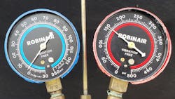
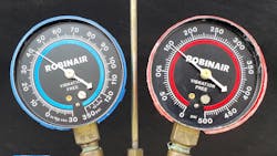
The variable displacement compressor will run at full capacity if the evaporator is entirely restricted or close to it. This means that the compressor will apply maximum suction on the low side without any refrigerant to suck and push whatever it can, as hard as it can out the discharge side. Therefore, the suction pressures are low, and the discharge pressures stay close to normal (Figure 6).
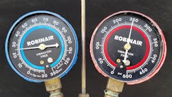
A suction side restriction between the service port and the compressor will produce a higher-than-normal suction side pressure (Figure 7). Since it's also a suction side restriction, it will affect performance the same as an evaporator restriction, although the effect on suction side pressures is just the opposite. This is because the restriction is downstream from the service port, so the compressor's suction is blocked. The only influence that the compressor has on the service port is discharge pressure, which raises the pressure. In this scenario, the discharge pressure will be slightly low because less refrigerant is flowing to the compressor.
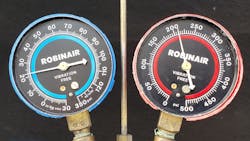
When a restriction is in the discharge line between the condenser and the high side service port, pressures will look reasonably normal (Figure 8). The discharge pressure will read a little high, and the suction pressure might be lower than expected. This can make a discharge line blockage hard to diagnose since pressures change so much with ambient temperature. You might not even notice the slight change in pressures caused by a discharge line blockage.
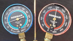
A stuck closed TXV will create a suction side restriction at the evaporator (Figure 9). A stuck open TXV will cause the system to react to a possible evaporator freeze-up condition. The low temperature of the evaporator will cause the PCM to cycle the A/C clutch more than usual. The erratic suction side pressures at the compressor will cause the VDC to change displacement frequently. If it seems like things are going a little haywire when analyzing a VDC system, check for a stuck open TXV.
Not all air conditioning woes are caused by the climate control system. Low airflow through the condenser can cause extremely high pressures (Figure 10). If the radiator cooling fan is inoperative on a hot day, discharge pressure can easily reach 500 - 600 psi, opening the A/C pressure relief valve on the rear of the compressor. You'll know this happened because you'll see oil all over the compressor, and the refrigerant will be almost entirely depleted.
Active grille shutters are located in front of the radiator and allow the PCM to control airflow through the radiator and the condenser. Airflow is vastly diminished if the grilles are stuck in the closed position. I found the grilles wired shut on an Escape, repaired at a body shop. They were broken and rattling, so the body shop fixed that problem.
A blockage in the front of the radiator (whether it's the grille shutters or an assortment of autumn leaves) causes two problems: low airflow through the condenser and an engine overheating event. Both of which can make a cold A/C system turn warm.
Just a few tips:
- VDC compressors use Polyalkylene Glycol (PAG) Refrigerant Compressor Oil YN-12-D. This oil may have some dark streaks and seem a bit discolored. This is normal
- It is not necessary to recover the refrigerant when replacing the ACP sensor. A Schrader valve behind the sensor will close when you remove the valve
- Disconnect your gauges when checking a system for leaks. You can't see a service port leak if it's covered by a coupling
- Humidity does affect refrigerant pressures. The pressures I present in this article are based on the relative humidity of about 45%. You'll find that humidity has nowhere near the effect on pressures that ambient temperatures do, but pressures will slightly rise as humidity increases
- Don't forget your basics
I hope you walk away from this article ready to tackle a Ford variable displacement compressor issue. The thing is that the VDC compressor will not cause most VDC issues you see. The fault will most likely be related to the fundamentals of basic air conditioning theory. Pull the codes, read the shop manual, and trust your knowledge of basic climate control. Keep cool.
