Content brought to you by Motor Age. To subscribe, click here.
What you will learn:
•Man-made faults cause some of the most difficult -to-solve symptoms
•Referencing service information will allow you to build a structured plan of diagnostic approach
•Bypass testing allows you to prove whether a repair will solve the actual symptom
I was called to a local body shop to look at a 2017 Cadillac Escalade for a customer. Over the phone, I was told that the vehicle goes into “limp mode” ever since he had it at a mechanical repair shop. He mentioned the shop broke a connector for the rearview mirror, and ever since then the vehicle would have a bunch of warnings on the dash, the steering effort would get hard, and the truck would go into a "limp mode." From what he was saying, this sounded like a simple repair - fix the connector, look like a hero, collect money, and move on. Since you are reading this, you can probably tell that is not how it went…
The saga begins
This Caddy has one of those newfangled mirrors with a compass and a video screen that appears when reverse is selected. As I was told, the harness side of the connector was destroyed. The coaxial cable for the video screen was destroyed as well. The shop owner then informed me that the broken harness was only available with the complete headliner, so he did not want to replace it if he didn't have to.
I decided to hook my scan tool up to the vehicle to get a baseline. I always run a complete scan of a vehicle as a rule (Figure 1). This lets the vehicle tell me a story. I have been burned too many times by vehicles with cascading failures caused by a component that is unrelated to the original complaint. I was confronted by a plethora of communication codes. As I was reading through this quick test, I felt myself at the top of a steep hill holding a snowball.
I decided to ask the vehicle owner to elaborate a little more on the vehicle's history. He explained to me that this is his personal vehicle that he purchased from a body shop that gave up on it (snowball was just released). Upon further questioning, he then told me that this vehicle had been a total loss, hit on every panel, and had some modules replaced (but which modules?) Good question: the best answer I could get out of him was "a couple".
The vehicle ran and drove, so I decided the best thing to do was to bring it back to my shop so I could spend some time with it to properly go through this thing. The first thing I decided to do was to get a diagnostic plan in order.
According to the test plan, I had chassis CAN codes, engine LIN codes, and broken wiring at the rearview mirror. I wanted to “reach for the low-hanging fruit." In this case, I literally had low-hanging wires, so I wanted to attack that first.
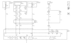
Pulling a wiring diagram, I could see exactly what is on this circuit (Figure 2). I could see the main voltage supply, ground, coaxial cable for the video signal, reverse signal, and a driver for the auto dimmer.
The voltage supply comes from the ignition main relay, the ground comes from G210, and the reverse signal comes right from the trailer backup lamp relay. Using some deductive reasoning, I can tell this mirror turns the screen on when it gets a signal from the trailer backup lamp relay. The signal is provided from the coaxial cable. The compass display is all handled internally at the mirror.
What is missing from that diagram? That’s right, no CAN bus wiring. There is no way this is causing the customer’s complaint (the snowball is starting to grow and pick up speed).
Avoid the mirage
It was time to consult the quick test again. There were a bunch of communication DTCs, and they were everywhere. I have had experience with this generation of GM trucks causing CAN DTCs with the use of aftermarket scan tools (that's another story), so I decided to hook up the OEM tool (the GDS2), and scan from there.
I ran the codes and cleared them (Figure 3). Reading the new results of the factory test, I saw that we had a bunch of DTCs for the chassis expansion bus being offline. This was reported in the power steering module, body control module, electronic brake control module, active safety module, and suspension control module (if the power steering module was down, that would explain the hard-steering symptom).
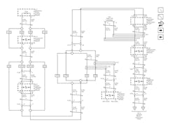
I tried to do as much research as possible before pulling anything apart. I decided to get a networking diagram for the chassis expansion bus (Figures 4+ 5). Reading this diagram, this seems like a typical GM daisy-chain CAN network, meaning for each module on the network, there are two CAN bus wires going in and two CAN bus wires going to the next module. There are also two 120-ohm resistors on the network (one at the beginning, and one at the end).
If you know me, you know I love to scope “all the things." If this is what you are looking for in this article, I regret to inform you that you will be sadly disappointed. This will be pretty low-tech. Anybody still here? OK, moving on…
The DTCs suggest I have a bunch of modules not talking. The best first-test for this is checking for a complete bus. Pins 12 and 13 on the DLC are for the chassis expansion Bus (Figure 4). Like with powertrain high-speed CAN, I should see 60 ohms between pins 12 and 13 because of the two 120-ohm resistors (Figures 4+5). Connecting my meter, I had between 0 and around 1,500 ohms. It’s safe to say that something was going on.
I get by with a little help from my friends
I remembered getting a network diagnostic lesson from Keith DeFazio (from New Level Auto). In the lesson, he taught me the best way to attack this is to split the circuit. The issue “should” be on one half of the circuit, and that would offer a diagnostic direction.
The closest (and easiest) testing location would be the steering angle sensor (Figure 4). Pins 1 and 3 go to one half of the BUS, and pins 2 and 4 go to the other half. I unplugged the steering angle sensor; pins 1 and 3 showed 120 ohms, while 2 and 4 had that strange reading.
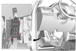
The next logical spot was downstream, the instrument panel junction block (Figure 6). This vehicle spent some time outside with the doors off, so there was a distinct possibility that the exposed junction block got wet.
The CAN wires come in on connector X5 and come out at X1. The X1 connector, pins 19 and 20, would be the best testing location (Figure 5). This required removal of the junction block. The X1 connector was in the back of the junction block; the pins on the junction block side tested at 120 ohms (a normal value). The harness side showed the strange ohm reading. It looked like I'd be moving further downstream.
The next item on the list was the multi-axis acceleration sensor. I did a check on the location of this module. According to the service info, it is located under the center console, right next to the airbag module. If you are familiar with GM consoles, you would realize It would be easier to check the next module in line -the left side seat belt retractor.
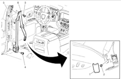
The seat belt retractor is part of the wound section of the seat belt (Figure 7). To get to it, I had to take off the front and rear sill plates on the driver's side. While I was removing the rear sill plate, I could hear electrical arcing, - not something you want to hear in a car with insulation all over the place.
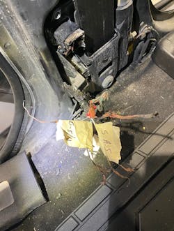
Once the covers were removed, I could see the extent of the damage (Figure 8). There was nothing left of the connector, and the harness was essentially a mound of burned copper. If you touched it, you could see the sparks from the wires.
This was a fire waiting to happen!
I quickly cut all the wires back where the insulation started again (after taking a picture of course). There was the problem!! This most definitely explained the chassis CAN bus codes. I 100 percent needed to replace the seat belt retractor and pigtail. I only wanted to make one call to the customer. Was this the only problem? We needed answers.
The way to check if a module is bringing down the bus (in this type of network) is to loop both CAN highs together and both CAN lows together, effectively bypassing a suspect-module). Typically, it’s pin 7 to 8 and pin 5 to 6, or in this case, twist the blue/yellow wires together and the white wires together.
BAM! the chassis expansion bus would now talk (Figure 9). The only thing not talking was the left-side seat belt retractor (I would need to install a new pigtail). So, I measured the resistance of the CAN bus wires to the junction box and labeled them (Figure 10).
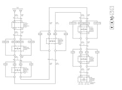
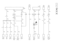
I ran a new quick test and cleared the DTCs, then reran the test to see what was left. The only issue that was of concern to the customer and me was the LIN bus code stored in the engine control module. Looking at the LIN bus network diagram (Figure 11), the only LIN component reporting to the engine module is the radiator shutter motor.
This required another call to the shop. According to the customer, this was the original reason the vehicle went to the last repair shop. The previous shop requested them to replace the shutter motor, and the customer obliged. The code is a hard one and will not erase.
Is this a faulty new component?
I needed to hear more about this previous repair. He had a DTC for the fuel gauge circuit, and they replaced the sending unit and repaired a wire at the PCM.
With this new information, I wanted to start with the basics. In a situation like this, you need to treat this separate issue as though it’s unrelated. Start over, like this is a different vehicle. There is a LIN component not communicating… K.I.S.S. (keep it simple, stupid).
What does a module need to communicate? Voltage, ground, and communication wire(s). It’s as simple as that. This grille shutter is hidden behind the bumper cover but in front of the radiator support. I did not want to take the bumper off unless I had to. According to the diagram, connector X106 is accessible. Back-probed, there was sufficient voltage and ground supply. There was also about 6-7V at the LIN wire when the truck was key-on. That voltage means very little to me while using a meter. It tells me that something is happening, but very little as to what.
Generally, with LIN bus, you will have a master and slave module that will output (nearly) a 12V to (nearly) 0V square wave. Sometimes the slave will wake up and transmit;, sometimes it won’t. The master will always transmit, waiting for an answer from the slave module(s). I was too lazy to walk two feet to my scope, so I unplugged the X106 connector. While testing, the PCM side of the harness is dead on the LIN wire.
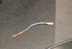
I examined the PCM connectors. I could see where the previous shop repaired the fuel level gauge wiring. The "repair" was covered by a little tape. When I say “covered,” I mean it was a piece of tape pressed together over the wire. I removed the tape to re-wrap it. The wire and pin came out of the connector with the tape. THE ENTIRE WIRE AND PIN!!! (Figure 12).
I had to then disconnect the X1 PCM connector, reinstall the pin, and solder the wire back together. While I was there, I wanted to check the LIN wire to the grille shutter but couldn’t see the pin. The wire went into the back of the connector, but the pin was gone. I removed the locking cap to the connector, and clear as day, I could see the pin for the LIN wire backed out (Figure 13).
I soldered and reinstalled the fuel level wire and pushed the LIN wire back into place. The locks did not engage. Upon closer inspection, the pin locks were broken. This vehicle needed a PCM connector. To verify my diagnosis, I reconnected the X1 connector and pushed the pins in. To nobody's surprise, the LIN code went away.
The verdict is in
I was then able to recommend repairs. This vehicle needed a seat belt tensioner, pigtail, and a PCM connector. The customer authorized the seatbelt tensioner and told me that he would find the PCM connector and wire it in himself.
With the seat belt tensioner repaired and installed with the repair pigtail, I was able to program it and clear all the chassis bus DTCs. The dash had no more warning messages on it and the system never went into limp mode.
The customer decided to live with the broken wires in the rearview mirror until he felt like replacing the headliner. I taped up the exposed wires and reassembled the vehicle. The customer was happy to be able to finally drive his newly acquired Escalade!
There is no greater challenge than man-made faults. But when you are dealing with a series of them on the same vehicle, the difficulty factor is multiplied exponentially. However, keeping your cool and having a solid plan of attack is what it takes to decipher the faults and come out with your superman cape flapping in the wind.
