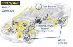
Electronic stability control (commonly referred to as ESC) is designed to slow and control the vehicle from unwanted oversteer and understeer. An ESC system takes advantage of the existing ABS and traction control systems.
The system monitors individual wheel speed (providing data relative to any individual tire losing traction), engine speed, steering direction and the degree of lean and roll being experienced at any given time. The objective is to help the driver maintain control of the vehicle to avoid front-end push (understeer), tail wagging (oversteer) and loss of traction. In essence, these systems were developed to aid the typical driver in maintaining vehicle control to avoid an accident. Let’s face it: the majority of drivers do not possess the skills to control a vehicle in extreme maneuvers. These systems step in to provide an automatic aid to supplement the driver’s abilities.
Beginning with the 2012 model year, automakers began in earnest to produce sophisticated ride control systems that enhance vehicle safety. Whether you refer to these systems as active or adaptive suspension systems (or any of a number of other labels that the automakers decide to use), a variety of electronic-managed vehicle stability systems are becoming increasingly commonplace.
In addition to, or as part of a stability control platform, shock dampers have become more sophisticated in terms of either damping control or self-leveling (or both) capabilities to control vehicle ride height through a range of vehicle speeds and road conditions.
Common examples feature small electric motors that are mounted to the top of the shock absorber rods. These electric motors (actuated by signals sent as a result of the monitoring data provided by various damping, pitch, steering angle and yaw sensors serve to turn the shock’s rods in order to adjust the shock’s valving (stiffer or softer) to accommodate current driving conditions. Other vehicle applications, found on many GM and European makes, employ a magnetic fluid approach wherein the magnetic-particle-laden hydraulic fluid changes viscosity depending on operating conditions.
Wear-related components are still key
The technological advancements in stability control currently in use and those coming down the road certainly contribute to vehicle control and accident avoidance, but all of the electronic techno-magic in the world can’t do its job properly if the vehicle’s tires are sub-standard. Electronic ride control and its attributes are dependent on the tire’s ability to provide the necessary degree of traction. If the tires can’t grip the road, the system can’t provide all of the intended benefits.
Regardless of whether or not your shop sells tires, inspect the vehicle’s tires for overall wear, uneven wear and age (dry rot and age-hardened tread compound. If Santa Claus’ reindeers can’t get off the ground, it doesn’t matter how many expensive toys are loaded on the sleigh...they aren’t going to be delivered. The same holds true for today’s vehicles equipped with electronic ride control. They may be adorned with innovative and complex systems, but if the tires aren’t up to the job, the customer won’t realize all of the benefits that these sophisticated systems are designed to provide.
The same holds true for various suspension system components such as springs, control arm bushings, lower ball joints, anti-sway bar links and bushings, etc. The vehicle may be equipped with electronic ride control system, but the condition of “traditional” wear-related components remains as critical as ever. Electronic ride control systems are management systems, and remain dependent on the condition of all wear-related chassis components.
[PAGEBREAK]
Magnetic ride control
Compared to conventional shock damping that relies on hydraulic fluid and control valving, a fairly recent development now being used by some auto makers involves magnetic ride control (the actual term is “magneto rheological” technology), which employs electromagnetic oils within the shock’s piston, comprised of a very sophisticated magnetic particle-infused polymer liquid. An electrical charge is delivered to the liquid (timed and controlled by an ECU that receives input data from a series of sensors), causing the magnetic particles within the fluid to change their shape, or density, which quickly changes the liquid’s viscosity (thinner when the system wants freer movement, thicker when damping needs to be more firm).
The special “magnetic fluid” can change from a relatively thin viscosity to an almost plastic state faster than you can flick your finger. This altering of the state of viscosity changes (or is capable of changing) at an astonishing rate of up to 1,000 times per second as commanded by the system’s ECU.
Roll stability control
Developed by Ford in 2003, and further refined with ongoing evolvement, a roll stability control (RSC) was added to piggyback onto existing electronic stability control (ESC), traction control and ABS. The RSC incorporates additional roll sensors that consider the vehicle’s chassis position relative to road angle, vehicle pitch angle, and wheel departure/lift. If the roll angle is detected to approach a potential rollover (vehicle load and center of gravity), the system will apply brake pressure to the outside wheels, helping to keep the inside wheels contacted to the ground.
A gyroscopic sensor determines body roll angle as well as roll rate. In conjunction with the vehicle’s lateral, front/rear pitch angle and yaw rate sensors, data is monitored 150 times per second. If roll angle and rate are detected at the predetermined limit, the RSC system activates, reducing engine power and applying the brakes as needed to specific wheel locations. Wheel lift can be detected with or without braking pressure. RSC is a further enhancement and addition to an electronic ride control system, specifically designed to detect and hopefully prevent a vehicle rollover. Naturally, this is especially applicable to vehicles with higher centers of gravity such as certain SUVs.
Adaptive suspension terms
Absorber control actuator: Small actuator motor connected to the top of the shock piston rod in an adaptive system where a signal from the ECU adjusts shock damping.
Absorber control ECU: Dedicated ECU for an adaptive suspension system.
AVS: Lexus term for their Adaptive Vehicle Suspension system.
CES: Tenneco’s Continuously Controlled Electronic Suspension system developed for a variety of OEM applications.
CDC: Continuous damping control (this is the term used for many of Ford’s European applications).
4-C active chassis: This is the term used for Volvo’s active suspension featured in the S60R and V70R models.
FlexRide: Term used by Opel for their active suspension.
Front acceleration sensor LH: Detects the vertical acceleration of the left front area of the body.
Front steering control ECU: This ECU sends the VGRS (variable gear ratio steering) operation angle signal to the absorber control ECU.
MagneRide: GM’s name for their magneto rheological systems.
Magneto rheological: A magneto rheological fluid is a highly specialized type of fluid containing dense magnetic particles that quickly changes viscosity when subjected to a magnetic field. This fluid can change from free-flowing to an almost solid plastic state by varying the strength of the magnetic field. When used to control shock absorber damping, it reacts very quickly, as fast as 1,000 times per second.
Rear acceleration sensor: This pitch angle sensor detects the vertical acceleration of the rear of the body. Under braking, this detects the angle at which the rear of the vehicle pitches upward.
Skid control ECU (brake actuator assembly): The skid control ECU sends the vehicle speed signal to the shock absorber control ECU as part of the data used to determine suspension damping. It also sends the brake pedal depressed signal to the absorber ECU. It sends a request for damping force control to the absorber ECU.
Steering sensor: The steering angle sensor makes the ECU aware of the steering direction and the angle of the steering wheel. This is yet another aspect of input information used by the adaptive suspension system to control shock damping.
Yaw rate sensor: The yaw rate sensor informs the ECU of longitudinal and lateral acceleration and deceleration (pitch angles). This is another integral bit of data fed to the adaptive suspension system in terms of detecting body movement.
[PAGEBREAK]
One example of an automaker’s electronic ride control system is found in the 2013 Lexus GS350. This system is referred to as an Adaptive Variable Suspension (AVS). Control actuators are mounted to the top of the struts/shocks. By monitoring the various vehicle sensors, the absorber ECU controls the actuators, varying the damping control of the hydraulic shocks/struts.
Monitoring and actuating components for the system include front and rear acceleration sensors, yaw rate sensor, steering angle sensor, skid control ECU, and the ECM (which sends a drive torque signal to the absorber control ECU).
The system sensors monitor body motion laterally (side to side), front-rear vertical acceleration (nose dive and nose rise, rear dive and rear rise), and body vertical motion.
Each of the shock absorbers feature an actuator that tailors the shock’s damping control, adjusting the ride control according to driving conditions.
Lexus absorber control actuators
The shock absorber actuators are mounted atop each shock’s rod, under the upper shock absorber cap. The actuator engages to the top of the shock’s rod, keyed to an internal damping adjustment driver. This is similar to an aftermarket shock that’s manually adjustable. In this case, electronic actuators turn the adjusters, commanded by the ECU as a result of information provided by the system’s vertical, lateral and longitudinal sensors.
Use a jumper wire to connect terminals 12 (TS) and 4 (CG) of the DLC3 diagnostic port. Turn the ignition switch to the on position. The “SPORT S+” indicator in the information display should blink in the Test Mode blinking pattern, blinking once every 0.125 seconds. If the display does not blink, there’s a problem with the indicator light.
Check the absorber control actuator operation. Starting with the SOFT position, depress the brake pedal. Using the Toyota/Lexus Techstream (or similar scan tool), check that the absorber actuator position increases by two steps, every time the brake pedal is depressed.
You should see the actuator position move from SOFT to 3, to 5, to 7, to 9, to 11, to 15, to 17 (the HARD position). Bounce the vehicle and confirm that the shock absorber(s) is getting stiffer on compression. Every time the brake pedal is depressed, the absorber control actuator rotates in 15-degree increments to a maximum angle of 120 degrees. If the actuator does not rotate, suspect the actuator circuit.
Once the inspection is complete, turn the ignition switch to the off position, and then disconnect the jumper wire from the DLC3. Then you can turn the ignition switch to the on position. If the ignition switch remains on after the jumper wire has been removed, the vehicle will remain in the Test Mode.
In order to remove the shock absorber control actuator, remove the shock cap and disconnect the actuator wire connector. Turn the actuator counterclockwise 40 degrees to detach.
In order to inspect the control actuator, use a multimeter to measure the actuator resistance. Citing the front actuators as an example, note that connections on the right front differ from that of the left front actuator.
In order to install the actuators, engage the actuator to the shock rod and turn the actuator clockwise 40 degrees. The rear shock control actuators are removed, checked and installed similar to the procedure used for the front actuators. ●
Checking the left front actuator:
Tester connection Specification
1 (FBL+) – 3 (E FL) 12.0 to 12.8 ohms
2 (FAL+) – 3 E FL) 12.0 to 12.8 ohms
4 (FBL-) – 3 (E FL) 12.0 to 12.8 ohms
5 (FAL-) – 3 (E FL) 12.0 to 12.8 ohms
Checking the right front actuator:
Tester connection Specification
1 (FBR+) – 3 (E FR) 12.0 to 12.8 ohms
2 (FAR+) – 3 (E FR) 12.0 to 12.8 ohms
4 (FBR-) – 3 (E FR) 12.0 to 12.8 ohms
5 (FAR-) – 3 (E FR) 12.0 to 12.8 ohms
For more from this author, see:
Engine sealing tips: How to avoid problems fron annoying leaks to devastating damage
Engine pre-oiling: A critical procedure for any fresh engine


