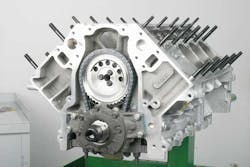
If you’ve never serviced the valvetrain of a GM LS-series engine, you’re likely in for a surprise when you remove the intake manifold and top engine cover plate, expecting to find the lifters and instead finding only a “bare” valley. The lifter bores (and lifters) are accessed through the top of the block in the upper area of the decks, requiring removal of the cylinder heads and cylinder head gaskets.
Let’s start by providing a bit of design background. The LS series of engines include both aluminum block (LS1, LS6, LS2, LS7, LS3, LS9) and cast iron versions (LQ4 and LQ9, primarily used in trucks and some SUVs). All LS-series engines feature roller-tip lifters, and all feature a 0.842-inch lifter body diameter. Instead of using “dogbones” or metal finger-trays to locate the roller lifters (to prevent lifter rotation in their bores), special LS-only composite plastic “lifter trays” are used.
These trays each hold four lifters. The cylinder block features large cavities above the cylinder bores for lifter and bucket placement. During assembly or disassembly, the lifters are held by the trays, allowing a complete set of four lifters and their tray to be installed or removed as a set (lifters and tray together).
Remember: Any roller lifter must not be allowed to rotate within the lifter bore, since the roller tip must remain in plane with the cam lobe. All roller lifter setups feature a method of keeping the lifters in register to prevent lifter body rotation. The LS engines simply use a different (plastic tray) retention approach. Flat surfaces on the lifters align within flat faced pockets in the lifter trays. This flat-to-flat engagement serves to keep lifters in plane with the cam lobes.
Bear in mind that, while the OE LS roller lifters are guided by these composite lifter “buckets,” there are a few aftermarket lifter arrangements that feature pairs of lifters that are “tie-bar” connected and do not use the OE four-lifter buckets. This is a modification performed by some engine builders. Considering the vehicles that your shop is likely to service, it’s unlikely that you’ll run into this. By-and-large, when servicing an LS engine, you’ll encounter the OE lifter system.
LS firing order
While consideration of the firing order isn’t particularly relevant when merely servicing lifters, I wanted to point out that the GM LS series of engines feature a different firing order as compared to early-generation smallblock Chevy engines. This is due to the different camshaft firing order, with cylinders 4/7 and 2/3 swapped in order to reduce valvetrain harmonics and to enhance both performance and smoothness.
FIRING ORDER EXAMPLES:
Smallblock/bigblock Chevy
Standard firing order 1-8-4-3-6-5-7-2
LS firing order (OE GM) 1-8-7-2-6-5-4-3
Install lifters before the head gaskets
Be aware that the roller lifters and lifter buckets must be installed before installing the head gaskets, since sections of the gaskets are located above the lifter buckets.
LS roller lifters may only be serviced (removed/installed) by first removing the cylinder heads and cylinder head gaskets. Removing the intake manifold and top engine cover plate is not necessary, since the lifters are not accessed within what you might consider as the “lifter valley” (as in previous generation smallblock Chevy engines). Lifter installation (with cylinder head and cylinder head gasket removed) will be the same regardless of your choice of OE or aftermarket lifters.
First soak the (clean) lifters in 5W30 engine oil for about 20 minutes. The lifters are then installed to the plastic lifter buckets. Simply orient the flats of each lifter body to the flats of the plastic bucket, and snap the lifter into the bucket. With four lifters attached to the plastic bucket, you can then ease the four-lifter bucket assembly into place, inserting the lifters as a group into their respective bores.
The lifter bucket is then secured to the block with a single 6mm bolt, which is tightened to 125 in.-lbs. (I prefer placing a drop of medium-strength thread locker onto the bolt threads). Once the lifter bucket is secured, you can then use a pushrod to gently push each lifter down for cam lobe contact. As you push down each lifter, you will hear and feel a slight “snap” as the lifter disengages from the lifter bucket’s detent and makes contact with the camshaft lobe. The lifter flats remain engaged in the buckets for proper lifter orientation (preventing lifter rotation). Remember: A flat tappet setup requires that the lifters be allowed to freely rotate within the lifter bores, whereas a roller lifter’s body cannot be allowed to rotate, since the roller tip must remain in a fixed plane relative to the cam lobe. That’s why all roller lifter-equipped engines will feature some sort of method to prevent lifter rotation.
In the LS family, the plastic “buckets” register the roller lifters to prevent rotation. Other methods of preventing roller lifter rotation (on other OE and/or aftermarket applications/engine types) involve either a pair of lifters connected by a pivoting tie-bar, or more commonly, each pair of lifters being guided by a twin-cavity “dogbone” plate, with these dogbones being held down by a common sheet metal plate that features tensioned “fingers” that prevent the dogbones from moving.
Note that some aftermarket performance lifters may be a tad longer (to allow for higher lift cams) and may require the use of a 6mm-diameter spacer washer between the lifter bucket and the engine block. If required, these lifter bucket bolt spacers will likely be supplied with the lifters. To prevent the spacers from sliding down while trying to align the lifter bucket bolt hole, I dab a bit of Royal Purple Max Tuff lube onto the back of the washers, which prevents them from sliding out of place. Any clean grease will likely suffice simply to secure the washer in place, but do not use any type of adhesive such as RTV, etc.).
[PAGEBREAK]
The clever aspect of the LS lifter buckets and their location is that this design allows you to perform a future camshaft change without the need to remove the intake manifold or the lifters. Simply loosen the rockers, remove the pushrods, and turn the camshaft one full revolution. This will nudge the lifters back into the buckets to the point where they’ll stay “stuck” in the bucket bores and away from the cam lobes. The camshaft can then be removed/installed without the need to remove the lifters and buckets.
This is one of the very cool advantages of the LS lifter design, allowing camshaft service without the need to remove the intake manifold and lifters (as in previous engine generations).
NOTE: While “popping” the lifters fully upward into their bucket retainers should secure the lifters away from the camshaft, you must avoid allowing any of the lifters from accidentally dropping (this would require removal of the cylinder heads, cylinder head gaskets and lifter buckets in order to then retrieve the dropped lifter(s)).
In order to absolutely ensure that this won’t occur, you can temporarily insert a pair of 1/4-inch or 5/16-inch-diameter rods (about 22 inches long each) into the oil galley holes that are adjacent to the camshaft bore, accessed at the front of the engine block (these are exposed once the front engine cover is removed, which is necessary in order to perform a camshaft change anyway). These rods will prevent any lifters from accidentally dropping through their bores. Once the camshaft has been reinstalled, simply remove these rods. CAUTION: When inserting these rods, install them gently. If you bottom them out with any degree of force, you might disturb the oil plugs at the rear of the block.
[PAGEBREAK]
Roller camshaft/lifter lubrication
As we all know, a flat tappet style camshaft and lifter faces must be lubricated with special high-pressure lube when first installed in order to aid the “break-in” of the camshaft lobes and their mating lifters. During initial engine firing (with a new flat tappet cam and lifters), the engine must be operated at a speed of about 2,000 rpm for the first 20 minutes or so in order to “mate” the lifters to the camshaft lobes.
[PAGEBREAK]
Many a new flat tappet camshaft has been ruined by improper break-in procedures. To add to the problem, in recent years, oil suppliers have removed or greatly reduced the amount of ZDDP (zinc dithiophosphate), which provided a high-pressure lubricant necessary for the friction experienced by flat tappet lifter faces and camshaft lobes. Part of the reasoning was that since all modern engines feature roller cams, the zinc phosphate wasn’t needed.
Today, dedicated break-in oils and high-concentrate additives are readily available for flat tappet camshaft break-in and long-term use. With that said, it is true that today’s hydraulic roller camshafts don’t require the same level of zinc phosphate. The same “break-in” procedure required for a flat tappet cam is simply not needed for a roller cam, since there is no tappet-to-lobe frictional mating.
However, if the engine has been altered with a performance camshaft and higher-rate valve springs, the increased pressures experienced at the rocker arm pivot and valve tip may need to be addressed by using an engine oil that does include acceptable levels of ZDDP.
Chances are, you won’t run into this, but if a vehicle enters your shop that appears to have been modified, it’s wise to ask the customer about the engine to determine if higher-rate valve springs have been installed.
This issue is more critical if OE rockers are in place (where the rocker tip slides against the valve tip), as opposed to an aftermarket roller-tipped rocker where frictional forces are greatly reduced. ●


