A variety of noise and vibration levels exist in the normal operation of any vehicle. When noises and/or vibrations are perceived by the customer, the vehicle ends up in your shop, and it’s up to you to determine the cause and repair. NVH (Noise, Vibration and Harshness) is the industry-wide term used when discussing these conditions.
The NVH condition that may concern a customer does not necessarily need to be the strongest vibration or the loudest noise. It could be one that has recently developed that the owner now notices. For example, tire pattern noise from a vehicle equipped with aggressive tread tires may be acceptable to the owner of a 4x4, but a complaint on the same vehicle could be much more subtle, caused by a driveline problem.
Because we sense vibration and sound using different senses, we tend to discuss them separately. However, vibration and sound are essentially identical.
A sound is a vibration or a “pressure fluctuation” of the air. Vibrations and sounds are both expressed as waves per second called Hertz (Hz).
Vibrations that are felt are under 200 Hz. Vibrations between 20 Hz – 20,000 Hz are audible by humans. Vibrations over 20,000 Hz are ultrasonic and are not audible by humans.
There are three major sources of vibration in an operating vehicle. These include the engine and engine accessories, driveline and wheels/tires. Each of these sources usually rotates at different speeds or frequencies.
EXAMPLES OF SYMPTOMS
While we don’t have the space in this article to discuss all potential NVH complaints, the following are specific examples of complaints and their likely or possible causes.
INSPECT WHEELS AND TIRES FIRST
Body shake, steering flutter and steering shimmy complaints all involve a pinpoint diagnosis of the same components. The condition of the component is what determines which of the symptoms occur. The wheels and tires offer a good starting point.
Tire and wheel inspection includes checking all four tires regarding manufacturer, size and specifications. Proper tire pressure is also an important item to confirm. Look for damage, deformation and wear. The technician should also rotate the tire and wheel assembly, inspecting both the sidewall and tread to look for obvious conditions caused by road damage, flat spots or runout. It’s also vital to inspect and feel the tread for unusual wear patterns that may have resulted from worn shocks, incorrect wheel alignment, etc.
While often overlooked, check the tire and wheel for proper bead seating along the entire bead circumference on both sides. An improperly seated bead will create a radial runout condition.
Check hub-to-wheel centering, to verify that the clearance is even and within the target value of 0.004 in. (0.1 mm) maximum. If the clearance is out of spec, rotate the wheel (wheel clock position relative to the hub). If the clearance is still out of specification, check the hub for runout to determine if the condition is in the hub or the wheel.
RADIAL FORCE VARIATION
In addition to dynamic balance of a tire/wheel assembly, we need to consider tire radial force variation (RFV) when diagnosing tire-related vibrations that occur at varying speeds and conditions. Ideally, the wheel should be phase-matched to align the tire’s point of maximum RFV with the wheel’s point of minimal radial runout (high point of the tire to low point of the wheel).
Radial force variation is a term that relates to a tire-sourced out-of-round/vibration that occurs, and masks itself as an imbalance vibration, only under dynamic conditions… when the wheel and tire package rolls in a loaded state. It must be noted that the term “radial” refers to forces applied at the radius of the tire, not to the type of tire construction. Radial force vibration could potentially occur with any type of tire, regardless of its construction (radial, bias ply, etc.). In other words, a radial force variation may prove to be the cause of a vibration that won’t reveal itself during a static or dynamic balance job, or by checking the mounted tire for runout in an unloaded state.
The radial force is determined by measuring loaded radial runout. On an average passenger car tire/wheel assembly, 0.001-inch of loaded radial runout is equivalent to approximately one pound of road force. For example, a measured 0.030-inch of loaded radial runout (about 30 pounds of road force) will cause the same amount of vibration as 1.5 ounces of wheel imbalance at 50 mph, which is five times greater than the .30 ounce imbalance limit.
Tire makers usually supply a red dot on the tire sidewall, which indicates the tire’s maximum RFV, or highest point of radial runout. When mounting the tire, this red dot should be aligned to a white dot on the wheel (if the wheel is so marked). The white dot on the wheel indicates the wheel rim’s minimum radial runout point (on a steel wheel, a dimple may be featured that indicates the wheel’s low point). When using alloy wheels that don’t feature a white dot, the tire’s red dot should be aligned with the valve stem, as this should be the minimum radial runout point.
A yellow dot may be found on the tire sidewall which indicates the lightest point of the tire (in terms of weight from a balance consideration). If a yellow dot is found, this should be aligned to the wheel’s valve stem, which should be the wheel’s heavy spot in terms of balance.
Even if dynamic wheel balance (from a standpoint of weight) is correct, misalignment of the red and white dots will likely result in a vibration complaint. On OE tires and wheels, always align the red tire dot and the white wheel dot (or valve hole, in the case of alloy wheels) when mounting. If the tire features a red dot and a yellow dot, the red dot is more critical and should be aligned with the wheel’s low point (dimple or valve stem).
Red dot on the tire: Align to the wheel’s low-point dimple (steel wheel) or to the valve stem (alloy wheel), or to a white dot on the wheel if the wheel features a white dot.
Yellow dot on the tire: Align to the wheel’s valve stem.
Both red and yellow dots on the tire: The red dot takes precedence. Align the red dot to the wheel dimple or valve stem.
However, it has been found that aligning the red dot on the tire to the low radial runout point of the wheel doesn’t always correct a potential RFV, although in theory, it should. The use of a load force machine is the most accurate method of correcting for RFV.
When a customer complains of a “tire vibration,” although the root cause may simply involve a static imbalance, other factors may be at play, including a static radial runout of the wheel and/or tire, a suspension/chassis problem, or a dynamic-only runout condition, known as radial force variation of the tire.
If the static imbalance is the culprit, this is easily cured by balancing the tire/wheel assembly. If runout is the cause, this can be cured by replacing the faulty wheel or tire; or possibly by match-mounting the tire/wheel package. However, when that approach does not fix the problem, the technician must begin a diagnostic approach in order to locate the cause.
RADIAL RUNOUT
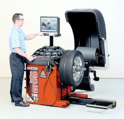
When a “mystery” vibration enters the shop, approach the problem in a systematic manner to eliminate possible variables. Naturally, check the tire/wheel assembly for balance on your shop’s balancer. If dynamic balance is verified, begin measuring for excessive runout. First, check hub runout in order to identify or eliminate the hub as the possible root cause of the problem. With the wheel/tire removed from the vehicle, check the runout of the hub. This can be tricky because of clearance at the wheel studs but can be accomplished with enough patience.
If the wheel is hub-centric (where the wheel relies on hub centering at the wheel hub hole to the hub protrusion), you’ll want to check the runout of the hub itself, at the contact area for the wheel’s center hole. If the hub center protrudes far enough from the wheel studs, mount the dial indicator so that the plunger contacts the hub surface. In some cases, it may be necessary to remove the wheel studs to gain access to the hub contact area. Pre-load the plunger slightly and zero the dial. Rotate the hub slowly, watching for runout on the gauge.
HUBCENTRIC AND LUGCENTRIC
The terms hub-centric and lug-centric refer to the manner in which the wheels center onto the hubs. If the wheel relies on centering at the hub, it’s hub-centric. If the wheel relies on centering by the fastener locations, it’s lug-centric.
If the wheel is not centered onto the hub, radial runout will occur, resulting in a vibration/bounce. Some aftermarket custom wheels that are designed for hub-centric centering may be made with a large center hole that will accommodate the largest hub in a certain vehicle application. In order to adapt the wheel (and retain centering), hub-centric rings are required (for example to reduce the hub hole from 88 mm to 72 mm, etc., in order to center onto another vehicle make/.model. If the hub rings are not installed, and the wheel center hole is larger than needed for the hub in question, you can’t necessarily rely on the fastener locations to properly center the wheel on the hub.
Multi-pattern wheels are available in the aftermarket, designed to provide fitment to more than one bolt circle dimension. While some of these wheels feature multiple bolt holes (for instance, ten holes where the application is intended for a 5-bolt hub), some multi-pattern wheels feature oblong lug holes, designed to accommodate more than one bolt circle. Instead of the holes being round, they’re oval-shaped, allowing mating to likely two-bolt circle diameters. In theory, these wheels should be hub-centric so that the wheels are properly centered to the hubs. These wheels are not very common today, but if you encounter them, extra attention to wheel centering is a must. After mounting to the hubs, check for radial runout (visually at first, then with a dial indicator). Inexpensive aftermarket wheels may feature slightly oversized bolt holes and oversized center holes, which can easily create a radial runout condition, resulting in a “thumping” vibration.
Check hub-to-wheel centering, to verify that the clearance is even and within the target value of 0.004 inch (0.1 mm) maximum. If the clearance is out of spec, rotate the wheel (wheel clock position relative to the hub). If the clearance is still out of specification, check the hub for runout to determine if the condition is in the hub or the wheel.
While we’re considering wheel centering, it’s important to note that if the wheel is centered improperly on the balancer, and installed properly centered on the hub, or if properly centered on the balancer but improperly centered on the vehicle hub, a vibrational problem is bound to occur. If the wheel does not provide a precise “slip fit” onto the hub (being centered by the hub/hub-centric), extra care needs to be taken to center the wheel during installation. This situation can be common for some budget-level aftermarket wheels.
SHIMMY
Wheel shimmy (steering wheel right/left oscillation) can be caused by a number of variables. Follow an organized step-by-step inspection:
Inspect the tires for excessive and uneven wear, and inspect for tire structural damage (badly deformed sidewall, etc.). Poorly constructed tires or damaged tires where plies are misaligned or separating can cause a shimmy/vibration. Check the tire and wheel for proper bead seating along the entire bead circumference on both sides. An improperly seated bead will create a radial runout condition.
Inspect and adjust tire inflation pressure. Low or uneven pressures on the same axle can cause pulls or wander.
Check for lateral runout. Using a dial indicator at the wheel rim, slowly rotate the wheel (on the vehicle) a full 360 degrees, noting maximum lateral runout. If excessive lateral runout is found, don’t automatically blame the wheel, since runout may be the result of hub or rotor runout and/or a stack-up of tolerances between the hub, rotor hat and wheel.
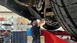
Before removing the wheel/tire assembly, with the suspension unloaded, check for wheel bearing looseness by rocking the tire inward/outward at the 12 and 6-o’clock positions.
Remove the wheel/tire assembly and inspect the wheel fasteners (studs and nuts or bolts, depending on design). Damaged threads can be an indication of abuse/over-tightening which can contribute to wheel/hub distortion.
Inspect the mating faces at the rear of the wheel, rotor hat and hub face. A buildup of corrosion can cause a lateral runout condition. Clean all surfaces as needed.
Check for lateral runout at the hub itself.
Inspect the wheel rims for damage (bent rims, signs of pothole/impact damage).
Check/adjust each tire/wheel assembly for dynamic balance.
Inspect the entire steering and suspension system. Looseness (caused by wear, damage or improper installation) can contribute to a shimmy, in addition, to wander and directional pull.
On the alignment rack, measure all angles, paying particular attention to caster angles. An excessively positive caster (caster angle beyond factory specification for the specific vehicle) can promote a shimmy condition.
During reinstallation of wheels to the vehicle, always use a torque wrench and follow both the specified torque value and tightening pattern. Uneven or excessive clamping torque can result in lateral runout, especially when dealing with thin-hat brake rotors.
ACCELERATOR PEDAL VIBRATIONS
Accelerator pedal vibrations occur at frequencies associated with engine speed. They are usually of low amplitude and not in the direction of the pedal stroke. They can usually be duplicated when the engine reaches a specific RPM regardless of vehicle speed. If the vehicle is moving, the vibrations will go away when coasting in neutral.
Pinpoint diagnosis includes inspection of the engine running condition at the RPM recorded during verification; idle quality (both normal and under load); fast idle quality both normal and under load; and cruise RPM. The pinpoint inspection also includes checking the engine, transmission and accessories for contact with the body; throttle lever and accelerator cables; and the accelerator pedal itself.
ENGINE NOISE
Engine noise is engine-speed related and may require a change in load. Engine noise is most commonly diagnosed by searching for the source visually or with a stethoscope. Other techniques such as removing a plug wire and grounding it, or disconnecting an injector can help identify the location of internal engine noise. By changing the firing load in a cylinder, noises from a piston, piston pin or rod bearing condition may change, identifying a cylinder causing the complaint.
Vehicles with multiple belts can be diagnosed by removing the belts one at a time until the condition changes. Accessories associated with the belt and the condition of the belt should be checked. Components (depending on the engine design) may include the fan, fan shroud, alternator, water pump, A/C compressor, idler pulley and power steering pump.
The air intake system can also be a source of both noise and vibrations. This system is designed to deliver filtered, fresh air to the engine with minimal noise. Many systems incorporate resonators to accomplish noise reduction.
A technician can inspect the air intake system for the proper components to determine if the complaint can be modified by pushing on or disconnecting components or hoses; for proper mounting and mount condition; and for foreign material that can make noise or cause an obstruction
SHIFT LEVER VIBRATIONS
Shift lever vibrations are generated by engine torque fluctuations or imbalance of revolving or reciprocating engine components (crank, rods, pistons). They may occur at particularly high engine RPM and may be amplified by an imbalance in the propeller shaft or shaft joint angle on an FWD vehicle. They may also be associated with a “buzz” sound.
Check the engine and transmission mounts for overall alignment, contact or looseness at mounting points, mount clearance and deterioration of rubber quality due to an oil leak.
CLUTCH SHUDDER
Clutch shudder can be reproduced during partial clutch engagement when the vehicle encounters rolling resistance. For example, this might include climbing a grade. This condition can be simulated by lightly applying the brake during clutch engagement. Don’t overlook the suspension components when pinpointing clutch shudder complaints as well. Suspension bushings can be inspected by prying them apart and checking the slits provided that are intended to minimize noise and vibration. The suspension system can be a transmission path for normal vibration during clutch engagement.
Also, check the condition of the rubber insulators at the top mounting point of struts. Excess movement of the strut mounting can cause transmitted vibration during clutch operation. The clutch pedal height, free play and movement also need to be checked while operating the pedal. A driveshaft can cause a clutch shudder condition. The driveshaft(s) should be checked for smooth operation without excessive free-play.
When external inspections do not produce the clutch complaint condition, an inspection of the clutch assembly is necessary. This includes the clutch release lever, checking for mounting, alignment and wear. The release bearing should be checked for proper alignment and smooth movement.
The pressure plate assembly and diaphragm spring should be inspected for wear, spring tension and alignment, evidence of heat that would affect spring temper and tension, evidence of discoloration or hard spots on the pressure plate and flywheel. Also check for scores, grooves or runout in the pressure plate or flywheel, warpage of the pressure plate mounting assembly due to uneven torque or loose mounting bolts, clutch disc surface condition, rivets, torsion springs and clutch disc female spline condition. Also, check the transmission input shaft male splines and pilot bearing/bushing.
TAKE-OFF VIBRATION
Take-off vibration occurs when the vehicle transitions from a stop to initial acceleration. It can be noticed in the dash, steering wheel (vertical movement) and floor on FWD vehicles. This type of vibration occurs at low frequency (15 to 30 Hz) for short periods of time and maybe extended by idling slowly up a hill.
Torque fluctuations are transmitted to the body through a range of potential sources. Check the exhaust system both when cold and when hot, since it will expand and contract with temperature. Check for overall exhaust system tension by inspecting the load currently applied to each rubber mount. Loosening the entire system to relax the tension, and retightening may be effective in resolving any complaints. Perform a basic inspection of the entire exhaust system for damage, alignment and components. If a replacement or aftermarket exhaust system was poorly installed, this could easily explain the cause of the complaint.
Before delving into diagnosing internal or external engine components, check engine mounts. Engine torque type complaints relating to mounts or contact can be duplicated by rocking the powertrain. This is done by increasing the RPM with the vehicle in gear, wheels blocked and brakes applied. Both forward and reverse gears should be used.
The driveshaft(s) should rotate smoothly without excessive play. Both conditions are sensitive to torque fluctuations.
Take-off vibrations that are felt in the floor may be produced by the driveshaft and transmitted through the transmission/transaxle. An inspection of drive shafts includes checks for play at the extension housing and yoke, missing weight (look for a trace of a spot weld), joint phase, smoothness and runout and center bearing alignment. In front-wheel drive applications, CV joints are targets for inspection.
ENGINE VIBRATIONS
Engines can generate multiple vibrations. First-order engine vibration is associated with the rotational force or torque. It is usually associated with imbalance or runout conditions such as in an imbalanced crankshaft, flywheel, torque converter or harmonic balancer. Engine firing or combustion will produce vibrations relative to the number of cylinders in the engine, in which case injectors and ignition components may be suspect.
BODY SHAKE/STEERING FLUTTER/SHIMMY
Body shake, steering flutter and steering shimmy complaints all involve pinpointing diagnosis of the same components. The condition of the component is what determines which of the symptoms occur. The wheels and tires offer a good starting point, especially if an NVH analyzer identifies this area as the generating force of the vibration.
BEATING OR PHASING GROWL
Beating or phasing occurs when two similar vibrations or sounds with slightly different frequencies exist in the same area or vehicle. Over a period of time, the phase of the two waves will change due to the slight difference in frequencies. At times, the two higher points overlap and create an even higher peak which raises the level or amplitude. Also, at times the two low points overlap to make an even lower point which lowers the level or amplitude.
This change in intensity or amplitude occurs in a repetitive manner at a constant vehicle speed as the phase of the wave changes over time. The resulting wave creates a sound called “beating,” which is associated with a vehicle having more than one tire out of balance. Tires are not always the same size during vehicle movement and will rotate at slightly different speeds due to tread wear, inflation pressure and loads.
Driveline vibrations are caused by imbalance, runout, CV joint or U-joint condition. The force from a driveline imbalance or runout will usually cause the first-order vibration because it occurs once per revolution of the shaft. Driveline complaints relating to U-joints are caused by phase, joint condition and/or working angle (inclination). As a U-joint rotates, it accelerates and decelerates twice per revolution. Therefore, conditions relating to U-joints will generate second-order vibrations.
Fourth, fifth and greater order vibrations can exist, but the first three are most common, noticeable and useful for diagnosis. If the technician identifies and repairs any of the first three vibrations, the remaining vibrations will also be reduced.
HARSHNESS
Harshness is the condition a customer senses when a vehicle contacts a single impact such as road irregularities, railroad tracks, speed bumps, etc. The level of impact that the customer senses depends on the type of vehicle suspension. A sports car suspension system may be designed for optimum handling and to give the driver a good “feel of the road.” In contrast, a luxury vehicle may be designed to provide the most comfortable ride possible, insulating the driver from unpleasant sensations.
A harshness complaint is relative to the type of vehicle involved and should be compared to other vehicles of the same type.
A vibration analyzer will not be the primary tool used to diagnose a harshness complaint, because the incident is momentary and difficult to isolate. A good visual inspection, starting at the location in the vehicle where the symptom seems to originate, will usually identify the component that has changed or deteriorated. When a harshness complaint appears, it is usually the result of a change in the path taken by the impact force. Examples include worn or missing bushings, over-inflated tires, broken or bottoming springs, worn or loose shock absorbers, etc.
WHEEL BEARINGS
Loose/worn or improperly installed front wheel bearings/hub-bearing assemblies can contribute to shimmy/wander, and will make proper wheel alignment impossible. Always check wheel bearing conditions prior to any alignment work, and be sure to measure hub flanges for lateral runout. Note that some bargain-basement-priced hub assemblies may feature short-lived bearings and may feature excessive lateral runout. High-quality, precision-made hub assemblies produced by reputable makers offer higher quality bearings and tighter runout tolerances to avoid NVH issues.


