Diesel repair: A combination of service information, tooling, and techniques will net the best results
What you'll learn:
- How 3 difficult repairs were ultimately resolved.
- What tools are required when repairing diesel engines.
- A pro tip/hack on how to get the job done more efficiently.
Modern diesel engine driveability diagnostics and repairs aren’t exactly the easiest to deal with, especially as systems continue to increase in complexity. Evaluating the training, information, and tooling needs of your shop, based on the vehicles you service, will allow you and your shop to best serve your customer base. There are countless compression, fuel, and sensor testing tools available; not to mention the multitude of specialty timing and injector tools. Taking a bit of time to analyze your specific situation will net you the best results.
Case study 1: 2021 Freightliner M2 – ABS light illuminated
A fleet customer brought in this Freightliner for routine preventive maintenance and a check-over. Initial inspection and health check showed that the ABS light was illuminated on the dashboard, our customary preliminary road test confirmed that the ABS was not operating as designed. A quick conversation with the customer revealed that they had not mentioned it as it was scheduled at the dealership under warranty, unfortunately, the dealer was backlogged for approximately two months.
Upon receiving approval from the customer to do some preliminary evaluation of the fault I grabbed my go-to scanner for HD — the TEXA Axone Nemo 1 — and performed a full system scan (Figure 1). The results showed a high-resolution wheel speed sensor (HRW) fault.
A quick evaluation of scan data showed that the front right wheel speed sensor was reading 161 mph (a default reading) whilst parked. Attaching the waveform generator from my Autel Ultra VCMI to the speed sensor harness (using the AESWave uTest terminal kit) and referencing service information, from Mitchell ProDemand Truck, allowed me to quickly verify the integrity of the chassis side wiring as well as the module. This combined with our fault code and data stream allowed me to quickly pinpoint a failed wheel speed sensor as the fault. A thorough inspection was performed of the hub assembly with the aid of my Snap-on BK500 borescope to rule out a mechanical failure leading to the failure of the sensor. The sensor was replaced using my favorite 1/4” drive set from SK Tools and a road test was performed to verify the integrity of the repair. Utilizing the right combination of information and up-to-date tooling and techniques allowed for a quick confirmation of fault and repair with a quick return to service for the customer.
Case study 2: 2011 Chevrolet Silverado 3500HD 6.6L (LGH) – Reduced power and failure to regen
Failure of a diesel particulate filter (DPF) to regenerate properly can be a frustration for both the customer and the technician. Diesel emissions control systems are becoming increasingly complex and therefore harder to diagnose given the multitude of inter-related systems and sensor inputs. The amount of data available makes it easy to overlook readings that may prove to be incredibly useful in correcting customer complaints quickly and effectively. As always, sound foundational knowledge of base system operation and access to the appropriate service information systems, be it OEM service portals or aftermarket providers such as Motologic, ProDemand, or AllData (for example, AllData has a large selection of OEM diagrams within their software) make the job substantially easier. The customer’s complaint was a familiar one for anyone working on later model emissions engines: engine de-rate and an inability to complete a regeneration event.
For this vehicle, I opted to utilize the OEM tooling for the truck, in this case, the Tech 2, and perform a preliminary evaluation which yielded two diagnostic trouble codes (DTCs): P2463 DPF soot accumulation and P0571 brake switch circuit 1. A few minutes in SI (service information) confirmed the code set criteria and the most useful data parameters to monitor. Scan data showed 86 grams of soot accumulation within the DPF and made it clear that this was an ongoing problem. Without delving too deeply into the diagnostic process, a quick check with my digital multimeter (DMM) of choice, the Snap-on Vantage, confirmed that the brake pedal position (BPP) switch was not operating correctly and as a result, the engine computer was seeing a regen abort signal. Replacement of the switch, once again going to my SK Tools 1/4” drive set, the dashboard displayed “Cleaning Exhaust Filter Keep Driving Until Message Is Cleared” yet within three to five minutes of driving the engine would enter reduced power mode again.
A service regeneration was then attempted in the parking lot utilizing the Autel Ultra and monitoring the data showed that despite throwing no DTC’s, EGT2 (exhaust gas temperature 2) was going open circuit intermittently and causing the regeneration to abort. EGT sensors can be difficult to remove at times, especially in the great northeast with our love of copious amounts of rock salt and brine. Grabbing a Cornwell Tools EGT sensor socket from my kit allowed me to remove the old sensor with ease and quickly install the new one (Figure 2).
Another service regeneration utilizing the Ultra proved the repair and the customer was back to work again. It’s not always a high-dollar specialty tool that gets the job done but rather the right tool for the job at hand, especially when it comes to finicky sensors in sometimes difficult-to-access locations. A small investment leads to many headaches saved down the road.
Case study 3: 2006 Ford F-350 6.OL – Extended crank/low power/intermittent stalling
A customer brought this vehicle in with a complaint of extended crank when cold and hot as well as low power and intermittent stalling. A visual inspection while performing a full system scan with my Autel Ultra showed major oil leaks on the top end of the engine as well as a loose air cleaner assembly. An aftermarket oil filter cap (tall) was also noted during this inspection — those of you familiar with these engines will know that when one mixes an aftermarket cap with an OE style filter, issues arise due to lack of proper compression of the anti-drain back valve in the filter housing. The information gained during a visual inspection can be invaluable when diagnosing a vehicle and putting together the pieces of the puzzle.
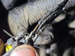
The full system scan reported multiple DTCs including: P0274:E0 Injector Circuit High, P0275:60 Cylinder Contribution/Balance, P0279:E0 Cylinder 7 Injector Circuit Low, P0528:60 Cooling Fan Speed Sensor No Signal, and P0470 Exhaust Pressure Sensor. A basic analysis of the wiring diagrams to get re-acquainted with system layout led me to the removal of the air cleaner and intake tube for a further inspection. This revealed rub-through damage to a main leg of the wire harness as well as oil damage to the insulation of the exhaust back pressure (EBP) sensor harness (Figure 3). Repairs were made to the wiring harness utilizing Bluepoint PWC7A wire strippers and a Milwaukee Tool 2488 cordless soldering iron and testing continued.
The truck still exhibited a long crank and low power complaint. Monitoring scan data confirmed that the system was struggling to meet the desired minimum 500 psi injection control pressure (ICP) and that the injection pressure regulator (IPR) duty cycle was running around 85 percent duty cycle (quite a far cry from the normal 22 to 28 percent) indicating either an IPR fault or a major oil leak.
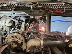
As someone who prefers to gather as much data with the least amount of effort, I pulled out two tools to delve deeper here. The first is an IPR controller, the OTC 6764, that allows me to manually control the IPR as well as the appropriate noid light (OTC Noid Light Kit 3054E) to install into the IPR pigtail of the engine harness (Figure 4). Scan tool bidirectional control could be used on it’s own here as but would still requires confirmation that the signal is reaching the IPR; this method tests both the solenoid and the harness/PCM (powertrain control module) at the same time. The noid light confirmed that the engine controller’s command was reaching the solenoid and the IPR controller confirmed that the solenoid was either not moving (or not moving far enough) to enable proper high-pressure oil build-up.
Teardown revealed contamination of the IPR that led to the seizure of the valve. This was a direct result of utilizing the taller aftermarket oil filter cap in conjunction with a shorter OE-style filter. This combination does not allow for proper compression of the oil filter bypass valve and therefore allows for quick oil drain-back to the sump as well as a complete bypass of the oil filter during engine operation. This puts an engine that is highly reliant on clean oil to operate correctly in a bit of a predicament, to say the least. Injectors 5 and 7 were damaged due to this unfiltered oil circulating the engine as well. Repairs, including installation of the proper OEM oil filter cap and filter, were performed with the help of the OTC 6770 kit and it’s IPR socket, glow plug, and injector tools. Oil filter cap was installed using a socket from the Lisle 13270 filter cap socket set.
Once again, the right combination of SI, tooling, and techniques led to a diagnosis and resolution of the customer’s complaint in an efficient and timely manner.
Bonus tip: Torque converter bolts trick
I’ve always been one who loves learning some of the inexpensive tips and tricks for getting a job done more efficiently. A trick I learned a while ago while I was working on trash trucks (mainly MR Mack trucks equipped with an Allison automatic) was to insert a cardboard paper towel roll into the access port on the bell housing when installing the torque converter bolts to avoid the bolts dropping down and creating a world of aggravation. Cheap? Yes. Incredibly effective and labor saving? Absolutely.
Even a simple trick like a paper towel roll serves to demonstrate that diesel diagnostics and repair can become more profitable by keeping up on training and tooling investments as well as fostering an innovative and problem-solving mindset in not only yourself but that of fellow technicians. It is not always the newest, shiniest, or fanciest tools that get the job done correctly but rather the right tool at the right time with the right mindset.
Tools used:
Service information system / wiring diagrams
Scan tools
Noid light
Digital multimeter
Back-probe kit
EGT sensor socket
IPR controller
Paper towel roll
About the Author
Christopher Groff
Chris Groff is a technician with Lykon Automotive in Pennsylvania and runs the Science of Diagnostics channel on YouTube. Groff began in the industry 15 years ago with an independent repair shop before attending the Pennsylvania College of Technology for Caterpillar diesel. After working with heavy duty trucks and John Deere equipment, he was drawn back to the automotive repair segment by ADAS and the continued advancement of technology.


