Don't replace the fuel pump until you've checked this!
You’ve determined that your customer’s concern is being caused by a fuel delivery issue. But before you replace that pump, are you sure that is the real cause of the problem?
If the circuit that supplies power and ground to the pump is not intact, replacing the pump with a new one isn’t going to change anything.
The first step is verifying the electrical integrity of the fuel pump circuit. As with any electrical concern, we start by reviewing the wiring diagram so we understand what is supposed to happen in the circuit.
Now, I’ll start my check by testing current flow in the circuit. After all, if the voltage to the circuit is correct and the resistance in the circuit is correct, electrically the current flow should also be correct.
One factor to remember though: Since this is a motor, the current it takes is also a reflection of how hard its working to move the fuel through the lines.
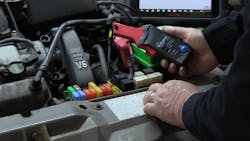
The easiest place to tap into this circuit for the vehicle I'm working on is fuse #16 in the underhood Battery Junction Box. I can use a fused jumper wire or a Fuse Buddy like this one to make it easier to place my amp probe.
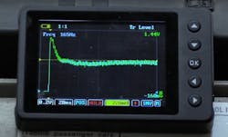
Next, connect the amp probe to your Digital Volt Ohmmeter and set it to the millivolt scale. Why? Your digital meter or even your scope can only react to a voltage input. The amp probe converts the current it measures to a millivolt output. In this case, 1 millivolt is the equivalent of 10 milliamps. I’ll need to make that conversion after I get my measurement. Typically, I would look to take my current measurement by using a fused jumper wire in place of the fuse that supplies power to the pump, or by jumping the appropriate terminals of the fuel pump relay. But in this case, the fuel pump is controlled by a Fuel Pump Control Module, very common today on the GDI engines you’re working on.
The easiest way to get this pump running is to operate it with my scan tool’s bidirectional controls.
To get the most accurate reading I can, I want to command the pump wide open - or as close to a 100 percent duty cycle as I can get.
If the current measured is higher than expected, there may be a short in the pump internally or the pump is not working hard - it could be no fuel is getting into the fuel pump module because of a contaminated filter or the fuel sending unit is reading incorrectly.
If the current measured is lower than expected, or no current is measured, the pump is either having a really hard time moving fuel or it could mean that there is a source of unwanted resistance in the circuit.
Time to perform a voltage drop test to determine which of the two it may be.
To perform this test, you can use your voltmeter or a PowerProbe. I like the PowerProbe for tests like this because it has leads long enough to keep me referenced to the battery - important when verifying the integrity of the entire circuit.
My first measurement is taken after connecting the tool to the battery. By depressing the switch used to apply power to the tool’s tip, I can get an OCV reading on the battery. I’ll need that number to see if all of it is making its way back to the pump.
The next measurement is under the car, taken as close to the fuel pump as I can get. In this case, it’s the connector just before the tank. I’ll use a backprobe pin to make contact with the connector.
Never force your meter lead in - you’ll damage the connector and make matters worse.
With the pump commanded on as before, I measure the power side of the circuit. It should read nearly, but not exactly, the same as the first measurement I took.
If it is significantly less, I have a source of unwanted resistance between this connector and the battery and I’ll backtrack until my reading returns to normal.
If the meter reading is correct, I’ll move my back probe pin to the ground side and repeat the test. This time, I should read nearly, but not exactly, “0” volts. Why?
Kirchoff's Law - simply stated says all the available voltage will be consumed by the resistance in the circuit - and the fuel pump should be the only real source present. If I read any significant amount of voltage now, I have a source of unwanted resistance between the connector and the ground side of the battery.
Time to check some grounds. But what if both readings are correct, but the current flow is still low? There is still a section of circuit untested - the portion from the connector to the fuel pump in the tank. The only option now is to drop the tank but at least, we now have a confirmed reason to do so - either the pump has failed or there is an electrical issue that needs to be repaired.
About the Author
Pete Meier
Former Creative Director, Technical | Vehicle Repair Group
Pete Meier is the former creative director, technical, for the Vehicle Repair Group with Endeavor Business Media. He is an ASE certified Master Technician with over 35 years of practical experience as a technician and educator, covering a wide variety of makes and models. He began writing for Motor Age as a contributor in 2006 and joined the magazine full-time as technical editor in 2010. Pete grew the Motor Age YouTube channel to more than 100,000 subscribers by delivering essential training videos for technicians at all levels.
Connect with Pete on LinkedIn.


