A look at network diagnostic tools and strategies
Content brought to you by PTEN. To subscribe, click here.
Our shop is known for our diagnostic abilities in the local area. Being confident in our abilities has much to do with the capabilities of our tools, and the know-how to exploit them. As such, we get many vehicles in to diagnose network communication issues.
We see everything from bad wiring, to bad modules on these vehicles, and sometimes as simple as a fuse missing. However, one technique that is common among all that we encounter is beginning our network diagnostic process with an in-depth interview with the client.
The beginning of the diagnostic journey
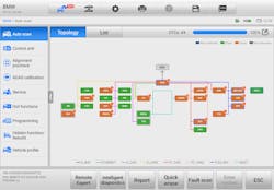
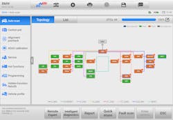
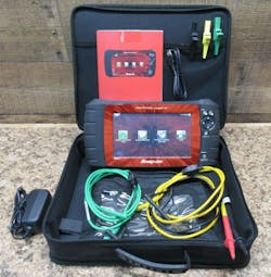
We are trying to gather as much information as possible to duplicate the client’s concern. We will then pull trouble codes from the entire vehicle. We prefer to use the Autel Ultra as it will also give us a network topology map of the vehicle’s communication systems (Figure 1).
Note: I do recommend consulting service information for the accuracy of the topology map as I have seen occasional errors with the topology maps. This includes both the information systems and scanners having errors. Sometimes, you will have to compare the vehicle to each topology map to determine which one is correct.
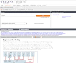
We will then check the vehicle service information, TSB’s, and Identifix for similar problems. I will not use Identifix as the “silver bullet”, but rather as guidance to a possible resolution (Figure 2). We will then follow-up with our on-vehicle diagnostics.
If we are unable to duplicate the client's concern, we will have a conversation with them about not being able to duplicate the concern, and that will affect the accuracy of the diagnosis. This could very well impact the amount of time the diagnosis takes, as well as create an additional expense. I always suggest to them to bring the vehicle back when they can consistently duplicate the concern and show me how to duplicate it for myself. This cuts down the diagnostic time dramatically and will save the client money.
To reassure the client, I will agree with them there is a concern between the bumpers, but if it isn’t acting up, there is no efficient way for me to locate the specific point of origin for their concern. I had one client some years back that didn’t believe me when I said that I couldn’t duplicate their concern and was getting angry with me for it. To simply defuse the situation, I politely asked them to go for a test drive with me.
They were very apologetic after the test drive. They explained to me the car had been vibrating all the time for the past several days, and even on the way to the shop. Once they went for a test drive and realized it had simply stopped, they understood.
Triangulating the fault location
When looking at the network topology map, you want to look to see which modules are on the different network buses. You are also going to look at the trouble codes to see which modules are reporting, and which modules are not reporting. This will help you to determine if you have a single module down, or if the entire bus is down.
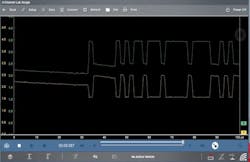
Part of your diagnosis may be disconnecting modules from the network bus to determine if that module failed. Always start with the most easily accessed modules or bus bars. Some of your diagnoses may also include checking the network at the module connector with an oscilloscope such as Snap-on’s Zeus (Figure 3).
You are looking to see if signal activity Is present and at the appropriate voltage levels. You will have to refer to vehicle service information, such as Mitchell 1 for specific network voltage levels, and in some case instances, "known good" waveforms.
We need to keep in mind that when we are looking at network communication, the speed at which communication occurs will not be able to be seen by a voltmeter. It simply doesn't have a fast enough sample rate. Also, remember that most voltmeters are average responding, which could be quite confusing if you don't consider that. On your slower networks, you can use Snap-on’s Vantage Legend (a 2-channel power graphing meter) (Figure 4).
If you do not have access to an oscilloscope, you might consider purchasing a logic probe. Be careful to get one fast enough for the network that you are working on. Knowing the network speed that you are working with, and the speed your tool is capable of are key to a successful diagnosis. We are on the verge of going to 10Gps automotive networks with 5G and “connected-cars” just around the corner.
Seeing is believing
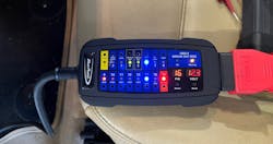
One of my favorite new tools for working on networks is the Blue Point EECTBOB (an intelligent OBDII break-out box) (Figure 5). The tool is a great provider of quick network status. It will show the system voltages and grounds. You can change the pin that you are looking at to see voltage levels, and it also has LEDs for each of the pins to visibly indicate activity. Most of your vehicles today will have multiple network protocols in use at any given time. Because of this, you must have the network topology map to determine which network the problem exists in, and how to go about diagnosing the problem.
In the example of a 2013 BMW X5, referencing Figure 1, we used the Autel Ultra to scan the vehicle. We were able to determine we had a problem with the flex ray network. We have trouble codes for no communication with electronic power steering, and we also have a trouble code for being unable to communicate with the PCM (DME). There were several codes in other modules for the flex ray network being down as well, so that raises a few questions:
- Why did we get the trouble code from the PCM for being unable to communicate?
- Why couldn’t we communicate with electric power steering?
The reason for this is that the PCM also communicates on PT CAN and PT CAN 2 buses.
Because the flex ray network is down, and that is the only network that it communicates on.
Isolating the fault
Our next step was to begin disconnecting easily accessed modules on the flex ray network and rescanning the network for communication. We started with the ABS module and also checked our network communication and voltages with our Snap-on Zeus oscilloscope. The voltages for the network at the ABS connector indicated there was no communication activity present, so onto the next module.
We then went for the electric power steering module mounted on the power steering rack. Bingo! We found battery voltage on one of the network lines, and we could see the other network line attempting to communicate. Further inspection revealed the network line had rubbed through and was shorting to a battery voltage feed.
We repaired the wires, rescanned the network, and we now had communication restored. By looking at the topology map, we can see all the other networks originated from the ZGM (which is our network gateway). You can think of a network gateway as the translator, so that all the different networks languages can share data.
Because of this, the breakout box would only allow us to see between the OBD-II connector and the ZGM module. All other tests would have to be done intrusively with an oscilloscope.
The second challenger
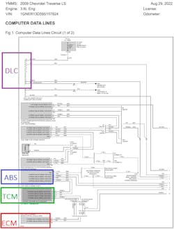
Next was a 2009 Chevrolet Traverse that came to us as a “no-start”. When we first scanned the vehicle, we were missing the ECM, TCM, and ABS modules. By looking at the initial network topology (using Mitchell service information), the ECM was at the end of the line followed by the TCM, and then the ABS module, just before it entered the passenger compartment (Figure 6).
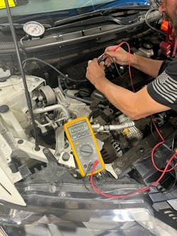
I scanned the vehicle with manufacturer-specific software to find out these modules were missing from the bus. My next step was to check the resistance of the network for the terminating resistors. I used my Fluke 233 digital volt ohm meter, with a magnetic detachable screen (Figure 7).
When I tested the network at the OBD port, It only measured 120 ohms. On a properly functioning network, It should measure 60 ohms (Remember, you need to power the network down and let it go to sleep before taking this test). This led me to believe I was missing one end of the network.
I then scanned the vehicle with global OBD-II and received information from the ECM. The information reported under global OBD-II, but in reality, it was coming from the fuel pump control module.
My next step was to go to the ABS module since that was the first one in line not reporting. At the ABS module, I found a broken retaining clip on the electrical connector. The connector was simply un-mated and was not making any electrical connection.
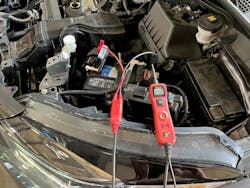
I checked for proper available voltage and grounds with my Power Probe 3 but only the voltage and grounds feeds (Figure 8). Never use a Power Probe on a computer data line. It is too easy to make a simple mistake and damage a module permanently. I find it useful when testing ADAS blind spot sensor powers and grounds because of the extended cord reach.
When it comes time to troubleshooting network issues, it boils down to a repeatable diagnostic process; to both locate and repair these faults quickly and efficiently. On some of the more difficult network issues, we have used a team approach. One person will do the physical work on the vehicle while the other person will be determining the diagnostic tests to make. We find this makes for a faster diagnosis, as each technician can stay focused on their specific tasks. Keep in mind you have to bill accordingly to cover the two technicians.
In closing, if you do not have the proper service information or tooling, it will be impossible to fix these vehicles profitably. Take the time now for training and give yourself enough time to look at the different systems with your diagnostic tools, so you know what good and bad will each look like.
