Navigating repair information: It’s for more than just R&R
Content brought to you by Motor Age. To subscribe, click here.
What You Will Learn:
• Leveraging repair information means a lot more than just installation instructions
• Many aspects of service information can not only quicken the repair process but educate as well
• Wiring diagrams and system description/operation should be referenced during each diagnosis
Many of you will roll your eyes, as I have said this repeatedly. Every technician needs a fundamental understanding of how things work: the appropriate and capable tooling to evaluate the components and the systems they make up, and last (but certainly not least), access to accurate repair information.
Like a three-legged stool, all three legs are necessary to be present if that stool is going to hold us upright. Well, imagine that same stool representing a day in the life of a technician. Then picture the legs of the stool representing the three variables mentioned above. If any one of the legs (the variables) is missing, it’s likely we will take a fall (Figure 1).
Most of my articles indeed revolve around the functionality of the system components and the tools and techniques to evaluate them, but today we will focus on the third variable, repair information. Repair information serves to be much more than just remove & reinstall instructions. It can and does offer a lot more:
- Torque specifications
- Programming/adaptation requirements
- Diagnostic flow charts/system description
- Wiring diagrams
- Component locations/Exploded views
- Connector views
- Expected values
- Examples of known-good oscilloscope waveforms
Each one of these specific areas serves a purpose and aids in my diagnostic approach. We will discuss the significance of each of them below.
Torque specifications
As simple to reference as it may seem, many technicians do not take the time to read instructions for proper disassembly and reassembly/installation of the components they are attempting to fix. Certain repairs are not as critical as others, but all fasteners are assigned a torque specification for a reason. Leaving a component’s fasteners too tight or too loose can have some devastating effects.
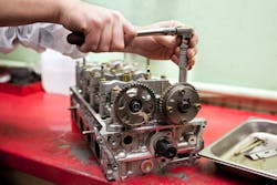
Understand that the torque applied to the fasteners is not the end goal. The torque we apply with our wrenches or ratchets/sockets creates the desired clamping force. This clamping force is the critical component. The applied torque (to the fastener head) simply infers how much clamping force will be produced. Something as simple as applying a film of oil to the threads of a bolt will allow more of a clamping force for the same amount of applied input torque. This can cause components to deform and be permanently damaged, leading to oil leaks and such. This of course could cause damage to engine internal components, for instance (Figure 2).
Programming and adaptation requirements
With the advancement in technology over the last 5-10 years, along with the capabilities we have been afforded in the aftermarket via the implementation of the Massachusetts Right to Repair Act (although it's far from perfect), we have access to OEM-level software and tooling. However, we do not necessarily have the same capabilities.
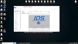
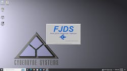
For instance, Ford Motor Company currently uses two forms of software platforms. IDS (Intelligent Diagnostic Software) was designed for dealership technicians and supports the full functionality of diagnostic coverage and programming for all its vehicles. The other system, known as FJDS (Ford J2534 diagnostic Suite), is a flexible diagnostic suite designed to work with J2534 devices and exists to satisfy the R2R mandates, a less expensive option (Figures 3+4).
Not taking the time to read and understand what the tools exist to provide could leave you in one heck of a predicament. For instance, a common scenario would be accepting a job for a replacement of a restraint control module (RCM). Having the less-expensive FJDS available would certainly allow you to perform that job successfully. However, it's the post-flash routine that must occur to get the vehicle back on the road safely. Unfortunately, the FJDS can't do that post-flash routine. Unless you are equipped with IDS or something else capable, you are stuck. Accessing proper repair information will alert you to what it takes to do the job in its entirety and correctly the first time.
Diagnostic flow charts
I once heard a fellow instructor describe diagnostic flowcharts as being good for one thing: toilet paper. As funny as that is, I can’t say that I agree (well, not entirely). However, I do believe I know what he was referring to.
Many technicians will follow a flowchart step-by-step. They do so somewhat blindly (as in, not understanding the steps, simply following orders). You have likely been disappointed with the results on occasion. Many times, you find yourself at the bottom of the chart with no resolution to the symptom in sight. This is a very common occurrence.
Those charts were written to help guide a technician to repair most situations on most of the vehicles (under factory warranty) 70 percent of the time. The engineers cannot think of every possible failure scenario. I have a solution, though.
Follow the flowcharts and understand what each step is trying to determine. Combine that with information about system description and operation. The flowcharts offer great supplemental input as well (like resistance values). If you are using this strategy with the three-legged stool approach, you create your own flowcharts that are far more practical and with less wasted time than those typically found in the repair manual (Figure 5).
Wiring diagrams
The wiring diagrams provide the overall view of the system, and I advise you to reference one before beginning troubleshooting any system, component, or circuit. Each one of these systems (when compared to other vehicles) may produce a similar outcome, but how that goal is accomplished varies between vehicles. The wiring diagram will allow us to see all the players in the game, decide where to make our preliminary tests for analysis, and just as important, prevent us from spending unnecessary time testing areas or components of the circuit we don’t need to be testing.
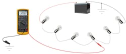
When possible, I like to divide and conquer a circuit. Picture a string of six light bulbs in series. One bad connection will leave the whole string inoperable. Testing for available voltage at Bulb #4 (about halfway through the string of bulbs) tells me the circuit fault is ahead of my test point (between bulbs 3-6) and not behind me (between bulbs 1-3). Continuing to split the circuit ahead of my current test location will be carried out until the fault is located (Figure 6).
Component location/Exploded views
To be used in tandem with the wiring diagrams are component locations and exploded views. Beginning first with the importance of component locations, being aware of where a component is will certainly help you to develop a logical diagnostic approach.
Considering the light bulb scenario in figure 6, the test itself is easy. However, I certainly would not be looking to split the circuit right down the middle if I had to disassemble the instrument panel to access it. I will be looking for an easier place to initially access it. If my logical testing guides me to then disassemble the dash, at least then I will have justification to do so.
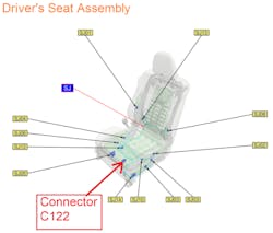
Exploded views offer similar information, and for the same reason. Being able to see exactly where a component is located offers a tremendous benefit for how we are going to access it for testing (keeping in mind, we are not looking to remove it/replace it, assuming I was looking to access a connector for testing.) However, that connector is located within the driver’s seat beneath the cover. I don’t wish to disassemble the seat entirely because I’m just testing a circuit. Exploded views can assist (Figure 7).
Connector views
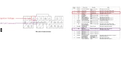
There isn’t much to say about connector views, as they don’t come in handy as some of the other pieces of information. However, they are an absolute lifesaver when you find yourself in need. Some as simple as a two-way connector can be troublesome. As when someone rewires the connector terminals in a reversed fashion, inadvertently. This is especially true because some faults like this appear to defy logic.
This PCM connector view allowed me to see how the connector terminals were arranged. Terminal #3 is in red and represents the ignition supply voltage. Just beneath it, in purple, is the terminal that carries the control signal to an ignition coil (Figure 8).
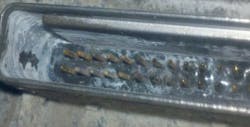
Water ingress created a resistive short between the two terminals. This caused ignition voltage on the coil control circuit (anytime the key was on) and led to the coil melting down (Figure 9). Any easy find with the proper information available to you.
Expected Values
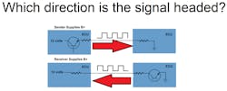
On occasion we will test a circuit and not know what it is we should expect to see. For example, a communication circuit between two computers may offer a 0-5V square wave. However, suppose the communication circuit is faulty. Testing revealed the circuit is displaying a steady 200mV. The question is which of the two computers outputs the voltage and which manipulates it (Figure 10)?
This issue is difficult to determine but an expected values chart will identify the circuit, the state of the ignition key (on/off/run), and whether to test with the connector mated or removed. This becomes particularly handy in situations like the one above. Ultimately it will help determine which of the two computers is at fault. Otherwise, you would be forced to take your best guess.
Known-good oscilloscope waveforms
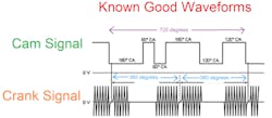
Many manufacturers, such as Toyota, have these lab scope captures within their repair information system. These captures that feature crankshaft position sensor signal/camshaft position sensor signal correlation can save a ton of time and often lead to a diagnosis of engine timing issues without ever having to disassemble the engine before repair. They’re truly a game-changer (Figure 11).
Why this is so important is that vehicles are getting more complex as time passes and at some point, we are going to need to know what a normal capture looks like so we can recognize a faulty one when new see it. Often, we are the pioneers, meaning no such known-good capture exists in your circle of connections and you will have nothing to compare to. That capture by itself and with nothing to compare to is useless to you.
If this data is published in repair information, there is a good chance of identifying a fault positively without having to first disassemble the engine.
So, as you can see, repair information is not what it used to be. Take the time to understand what your repair information can do for you. Leveraging the power of accurate repair information can and will increase your accuracy and productivity in the work bay.
About the Author
Brandon Steckler
Technical Editor | Motor Age
Brandon began his career in Northampton County Community College in Bethlehem, Pennsylvania, where he was a student of GM’s Automotive Service Educational program. In 2001, he graduated top of his class and earned the GM Leadership award for his efforts. He later began working as a technician at a Saturn dealership in Reading, Pennsylvania, where he quickly attained Master Technician status. He later transitioned to working with Hondas, where he aggressively worked to attain another Master Technician status.
Always having a passion for a full understanding of system/component functionality, he rapidly earned a reputation for deciphering strange failures at an efficient pace and became known as an information specialist among the staff and peers at the dealership. In search of new challenges, he transitioned away from the dealership and to the independent world, where he specialized in diagnostics and driveability.
Today, he is an instructor with both Carquest Technical Institute and Worldpac Training Institute. Along with beta testing for Automotive Test Solutions, he develops curriculum/submits case studies for educational purposes. Through Steckler Automotive Technical Services, LLC., Brandon also provides telephone and live technical support, as well as private training, for technicians all across the world.
Brandon holds ASE certifications A1-A9 as well as C1 (Service Consultant). He is certified as an Advanced Level Specialist in L1 (Advanced Engine Performance), L2 (Advanced Diesel Engine Performance), L3 (Hybrid/EV Specialist), L4 (ADAS) and xEV-Level 2 (Technician electrical safety).
He contributes weekly to Facebook automotive chat groups, has authored several books and classes, and truly enjoys traveling across the globe to help other technicians attain a level of understanding that will serve them well throughout their careers.
