Diagnostics can seem tricky and daunting at times. Just the sight of a “U” based code can be intimidating to even the best diagnostic technicians, but if a U0028:00 MOST bus code is set and you are dealing with the complaint of no center stack or no radio operation on a GM car or truck, where do you even start and what the heck is the MOST bus?
The Media Oriented System Transport bus (MOST bus) is a daisy-chain or ring configuration high-speed multimedia network system that allows transmission of audio, video, voice and data communication between modules (GM refers to these modules as nodes on the MOST bus diagnostic screens and data). It is used in many GM cars and trucks equipped with the new center stack Next Generation Infotainment system (NGI) starting in 2014. The MOST bus ring can have as many as 64 individual modules on it, but four or five are typical.
MODULE/NODES ON THE COMMON MOST BUS RING
The radio is the MOST bus master and will always be identified as node 1 during normal operation and all the MOST bus communications start and end with the radio. Because the radio is the master, it assigns each module/node a number on the MOST bus signifying its position on the MOST bus ring.
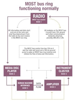
These numbers are ascending as the data flows downstream (see Figure 1). The radio also receives audio data from multiple circuits and devices (OnStar, satellite, digital radio, AM/FM antennas etc.) both on and off the MOST bus and acts like a gateway to other modules and systems on the vehicle using other vehicle networks.
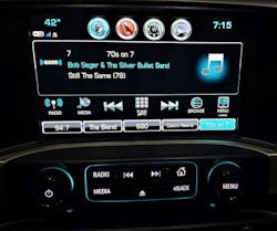
The Human Machine Interface (HMI) module is used for video for the NGI system, Bluetooth, USB data, SD Card reader, speech recognition from the onboard microphone, navigation module integration and the control panel touch screen.
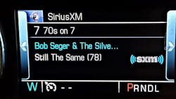
The Instrument Cluster (IC) module displays vehicle operating information (vehicle speed, engine information, driver warnings, etc.) audio output, audio input selection, phone integration and navigational information.
The Amplifier (AMP) is responsible for audio signals to the speakers, separating the audio frequencies (subwoofer for example) and the operation of active noise cancellation if equipped.
The media disc player is responsible for playing optical media.
MOST BUS CIRCUITS AND WHAT THEY DO
During normal operation each module on the MOST bus transmits and receives data downstream or counter clockwise via a twisted pair of MOST bus serial data circuit wires. All modules on the MOST bus will have dedicated power and ground circuits and are typically connected to other network circuits via General Motors Local Area Network (GMLAN) or Local Interconnect Network (LIN).
The MOST bus operation is initiated by a MOST control line that is connected to each module on the MOST bus and has 12V on it when the ignition is on or off.
When the ignition is switched on or accessory mode, the radio will provide a wake-up signal by applying a ground to the MOST control line. This wake-up signal will last for 100-milliseconds. As the wake-up signal is processed by the modules on the ring, each module will send a message to the next module downstream that it is awake and functional.
When the radio receives the information that all the modules are awake, are functioning properly and have been assigned a location on the ring, normal module MOST bus communications will start.
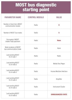
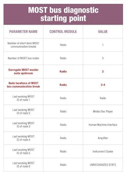
A functionally normal MOST bus ring could look like this depending on the options and vehicle configuration: Radio=node 1, CD player=node 2, HMI=node 3, AMP=node 4, IC=node 5. And the Surrogate MOST Master Node Upstream will have a value of none.
Note the radio should always be node 1 (see Figures 1 and 2).
Figure 1: This chart shows a normally operating MOST bus with five modules. Note the number of nodes. There is no surrogate master assigned and no communications breaks and the assigned MOST ID numbers. The value UNRECOGNIZED STATE means that there isn’t a module installed.
Figure 2: Normal MOST bus condition.
Photo 2. This is the instrument panel display, it shows radio, cell phone and other vehicle information and is part of the MOST bus ring.
WHAT HAPPENS WHEN THE RING BREAKS? AND WHAT DOES THE MOST BUS DO WHEN IT SENSES A BREAK?
When a node on the MOST bus ring does not receive data from the node before it, a ring break may have occurred (it keeps track of the number of breaks). But before a trouble code is set, the radio will try to make sure that all the nodes are awake. It does this by sending out the 100 millisecond wake-up pulse signal up to three times (with a two second delay between pulses) on the MOST control line. If after the third attempt, there is still no data received, the radio will send out a 300 millisecond pulse every 2.5 seconds on the MOST control circuit and the radio will set the U0028:00 MOST bus DTC.
Each module requires its own dedicated power, ground, MOST bus communications lines and a good connection to the MOST control line. If any of these circuits are missing they will cause a ring break. High resistance, an open, a short to power or a short to ground on the either of the MOST bus serial data transmit/ receive circuit wires can also cause a MOST ring bus break.
The last scenario for causing a MOST bus ring break is that the receive circuits inside a node can’t receive the data passed onto it from the previous node. The actual node may be awake and function properly but because it doesn’t get the data or can’t process the data from the previous module on the ring, the ring is broken.
Once a DTC is set the MOST system will start to perform a self-diagnostic, this diagnostic process takes about 10 seconds to complete. This will help pinpoint the area that needs attention without tearing the entire vehicle apart.
During the MOST bus self-diagnostic the radio will send data clockwise or upstream and assign diagnostic Node numbers ascending upstream with the radio now being Node 0 (this is completely backwards from normal operation). The radio will ask each module to respond until the data is stopped due to the fault in the ring. The last or farthest node/module away from the radio that reports an AOK message will now become the Surrogate MOST Master Node Upstream, and data flow will resume normal counter clockwise flow back to the radio.
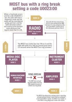
A MOST bus ring that is broken is represented like this: Radio=node 0, IC=node1, AMP= node 2, HMI=node 3, CD=node 4.
Note the radio becomes node 0 (see Figures 3 and 4).
Figure 3: This chart shows what the data will look like when there is a break in the MOST bus. It provides the information on where the break is located and what module is now the surrogate MOST master node upstream.
Figure 4: Example that shows where the MOST bus break occurred.
DIAGNOSTICS, THE TRICKY PART, BUT THE SYSTEM WANTS TO HELP US
Start with a full and complete module scan and note all the codes, codes in non-related modules may be clues to aid in our diagnostics. But if THE only complaint is no radio or the center stack is blank and there is a U0028:00 code, head to the Radio module. We are going to be looking for the MOST bus diagnostic starting point data.
Once we locate this data, it will provide us with information that should point us to the area that the MOST bus feels the ring is broken. It will provide information we can use such as; the number of nodes on the MOST bus and the last working node ID that is assigned to each module.
Using the vehicle build related (RPO) data sticker and the vehicles MOST bus wiring diagram we will know what modules are present and their location in the MOST bus ring. The combination of this knowledge and the MOST bus diagnostic starting point data should point us to the area that is causing the issue.
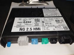
Photo 3. This is an HMI module from a 2016 GMC Sierra that would not communicate and was causing a no radio and blank center stack.
Let’s look at this 2017 Sierra pickup with a blank screen and no radio and code U0028:00
Looking at Figure 3 and 4 for visual aids we see the following.
1. We have a code U0028:00
2. The MOST bus diagnostic starting point data is indicating that the break is between Nodes 3 (HMI) and 4 (AMP). This is identifying the Node number in the normal flow of data direction: counter clockwise
3. The Surrogate MOST Master Node Upstream is Node 2 (AMP). This is the node number assigned after the MOST Bus has performed its own self-diagnostics (clockwise).
4. We now have a plan of attack: We know the break is happening between the HMI and the AMP and we know the issue is happening before the AMP because it is now the designated Surrogate MOST Master Node Upstream so the issue has to be before it.
5. At this point we should head straight to the HMI, checking basics, powers, grounds, connections, wiring continuity and using the scanner to see if it can communicate on any other vehicle networks.
NOTE: The communications wires that link all the modules on the MOST bus only attach the modules to each other. This means that the wire will have continuity but the when plugged into the module continuity can’t be measured because the module doesn’t actually provide a hard wired connection internally.
6. If all connections, etc., are OK, I would next remove the connector that contains the MOST bus data lines and either install the Bosch jumper test connector (I borrow them from our GM dealer) or carefully jumper the connection to complete the MOST bus ring eliminating the HMI module. Cycle the key and if the radio starts to play and the IP illuminates the installed bypass has completed the MOST bus ring, indicating the issue is the HMI. The center stack display will stay blank because the HMI is responsible for sending it video data but the radio will work.
7. After the repair is completed, in this case installing a new HMI module and flashing it with the latest software, we need to either perform a hard system reset by disconnecting the battery or removing the radio fuse or asking the scanner to reset the radio module to reset the communications error count and reset the MOST Bus Surrogate Master Upstream to none.
Understanding how a system works is almost as hard as the diagnostics now for many techs. The MOST bus system is one system that is difficult to get a hold of and intimidating at the start.
The terminology of the MOST bus is different and the fact that the nodes/modules actually change numbers to help in diagnostics is confusing. But with careful use of a good scanner, DVOM, information system for wiring help, RPO codes and some carefully installed jumper wires this system can be diagnosed efficiently and affectively.
MOST BUS CHEAT SHEET
- If a USB (flash drive with charge indicator) operates, or the push-to-talk functions, the HMI is likely OK.
- If all steering wheel controls (SWV) work, it’s likely not the IPC.
- If there is no door chime heard, or if the volume control does not work on the IPC, suspect the AMP.
- The MOST bus is not down if you hear audio and the clock is displayed. Suspect a bad display or a possible HMI software update.
- If the MOST bus breaks while driving the clock and the presets will disappear, but there will be a display.
- The bus is not down if the clock is displayed and you can hear audio.
