Why it's important to build and trust your diagnostic process
I wanted to tell a different kind of story today. There will be some good diagnosis, a lesson or two, and maybe even a little fun.
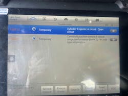
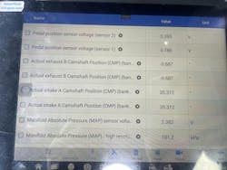
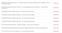
It all started as any other day, I was on the road doing some mobile diagnostics and programming. I received two text messages from a shop I do some work for occasionally. The messages were screenshots of some codes and pictures of some scan data (Figures 1+ 2).
Looking at these pictures, I could see that the vehicle in question was a Land Rover that had codes for Cylinder No. 5 injector circuit — open, and a Cam Position Sensor B Circuit range/performance code.
This was followed by a phone call from the shop owner. The vehicle was a 2018 Land Rover Discovery owned by a childhood friend of his. According to the shop owner, the vehicle owner noticed the vehicle was running poorly and decided to get it scanned. The shop he took it to made the decision the timing was off and recommended the engine be rebuilt. The vehicle owner approved the repair, and the shop sent the vehicle to a local engine rebuild shop.
The truck was at that rebuilder for a few weeks. When the vehicle owner called to check in, the rebuild shop relayed that they were having issues making the truck run correctly. They scanned it and sent the screenshots to the vehicle owner. The vehicle owner sent them to his friend, and then they made their way to me.
The repair shop (my client) then asked me to go to the engine rebuild shop and give them some direction — as they seemed lost with this Land Rover.
These vehicles need special tools to set the timing chains up correctly, and not using them can cause the engine to be out of time. I told the shop that I would go and check cam/crank correlation with a scope to verify timing and go from there.
This Should Not Be That Bad
I arrived at the engine rebuild shop. The vehicle is outside and someone is working on it. I can see the tech had the spark plugs all out of the driver ‘s side bank. This was going to be tough to work on. I started speaking with the tech and more of the story began to emerge.
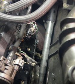
After the engine rebuild, they had the “camshaft code” that would not clear and the fuel injector No. 5 code that would not clear. When they inspected the No. 5 injector, they found it damaged and the internal wiring was exposed. They replaced the injector, but nothing had changed.
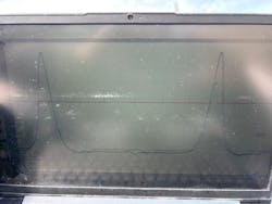
They asked me if I could check the operation of the cam sensor because they replaced it, but the code would not clear. I happily hooked up my Pico 4425a digital storage oscilloscope, removed the fuel control fuse, and cranked the vehicle. I saw a healthy pattern. I explained to them that this only meant the cam sensor worked. It won’t tell me the camshafts are in time unless I reference all the sensors.
The tech also stated that it was still running rough, and he could not get rid of the injector code. I hooked my scope leads to the fuel injector and cranked the vehicle and saw no signal.
I have learned the hard way that you need to verify your test equipment functionality each time you use it. I connected to battery positive and saw the scope display 12V — this meant my ground reference was good, my leads were good, and my scope was operating correctly. I hooked the lead to injector No. 4, cranked the engine, and saw a beautiful pattern.
Accessing the Big Picture
Ok, stop. This is where you need to take a step back and look at the entire picture. This vehicle is at an engine rebuilder shop — post engine rebuild. This engine was out of the vehicle. In layman’s terms, stuff was messed with. This injector harness goes to the back of the engine, joins up with the main harness, and terminates at the ECM, in the left side cowl panel. I need to check these wires to the injector.
Accessing the ECM is simple for this vehicle. I consulted a diagram and see that the No. 5 fuel injector terminates at pins 26 and 27 (Figure 3). According to the diagram, they are a twisted pair and should be simple to locate. Using an ohmmeter, I found the ignition wire had no continuity and the control wire was shorted to the ignition wire. This made no sense.
I was only asked to come to the shop in an advisory capacity. I advised the shop to check the harness for damage and repair anything they found. If they needed any help, I would only be a phone call away.
Fast-forward Two Weeks
I run a mobile ADAS, diagnostics, and programming company. I also have a brick-and-mortar location for jobs that get to be too much for the road. I was at the shop and a tow truck pulled up with a very familiar Land Rover on the back. I called the original shop that contacted me. He informed me that the rebuilders gave up and the vehicle owner asked him if he could figure it out (which means I get to figure it out).
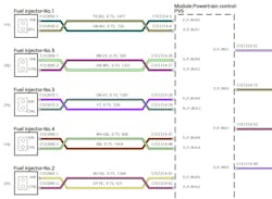
I got the vehicle in, cranked it up, and it ran...barely. It filled my entire shop with white smoke. It felt like it is running on only a few cylinders. It also had an extended crank. A code scan showed many more codes that were not there before — most notably a fuel rail pressure circuit, charge air pressure circuit, and injectors 1, 3, and 5 circuits. We decided to go after the fuel fail pressure fault first. Checking a diagram, we saw that the fuel rail pressure sensor and MAP (charge air pressure) sensor share a VREF (5V) signal (Figure 4).
Upon checking, the 5V reference source was not getting to either sensor, but it was coming out of the ECM (more broken wires). We checked the main harness and could not see where the rebuild shop opened it up. There also did not appear to be any apparent damage to it either. We started at the firewall grommet and removed a couple inches of tape. We found the green VREF wire broken. A simple fix of the wires now brought power to those sensors.
Like Magic, New Issues Appear
We then cleared the codes and started the vehicle. The extended crank was gone, but it still felt like it was running on only a few cylinders. Another code scan showed cylinders 1, 3, and 5 still open circuit. Hooking up the scope showed no signal coming from the ECM during cranking.
We cleared the codes again while the scope was still connected and cranked it again to see if the computer was shutting the coils down. Nothing ever came out of the computer. This makes no sense. This issue was not there two weeks ago, and as far as I can tell, the engine and harness appear to be in the same condition.
We pulled the ECM connector and checked continuity to the injectors. All the wiring checked fine. The injectors each had about 1.8 ohms, which is perfect for this vehicle. For some reason, the computer was not controlling the injectors. A check of the powers and grounds to the ECM was fine. We had no choice but to diagnose this as a faulty ECM. We called the repair shop, and the vehicle owner approved the replacement of the ECM.
The brand new ECM came in a few days later. We installed it and ran through the programming process with Topix Cloud DDA. The process went smoothly — until it asked me to start and run the vehicle. I cranked the vehicle, and the starter would not turn. It made a weird sound like the starter was binding or the engine was seized.
Let’s Not Get Lost in the Sauce
Rolling the engine over with a socket on the front crank pulley showed the engine was seized tight. It seemed hydro-locked. We removed all six spark plugs and started to roll the engine over again. The engine moved freely. Cylinder No. 5 was completely full of fuel (Figure 5) — followed by cylinders No. 1 and No. 3 having a decent amount in them. I had my tech roll the engine over in the suspect to measure the stroke and compare them to the good cylinders. Luckily, they all moved the same and there were no bent rods.
So, let’s recount: so far we have found damage in the wiring harness, damaged electronics in the ECM, and now three fuel injectors. We let the shop owner know the next batch of our findings, got it approved by the vehicle owner, and ordered three new fuel injectors.
We pulled the injectors out to replace them and saw that the O-rings and seals had not been replaced. For those of you not familiar with this engine, this is a direct injected engine: the fuel injectors run through the valve cover. This engine, just to remind you, has been rebuilt. The rebuild shop never replaced the Teflon seals — these are single use only! That’s a big no-no. We pulled all the injectors out, replaced the seals and O-rings, and installed the three new injectors.
With that much fuel in the cylinders, we decided an oil change was needed to get all of the fuel out of the crankcase. We popped the drain plug and out came seven gallons of fuel! This could have been caused by the stuck open fuel injectors, but I wanted to be sure. This engine uses two high-pressure (HP) fuel pumps mounted on the side of the engine. I have seen this style of pump fail before and leak fuel into the crankcase, causing fuel trim issues and misfires. Diagnosing this condition can be difficult. Most of the time you must rule out everything else and be left with only the fuel pumps as the remaining fault. This was not good enough for me.
Staying on Target
I had the assumption that one or both pumps was leaking directly into the crankcase — how can I test that? These pumps are driven from a separate cam by the timing chain on the right lower side of the engine.
The pumps are fed pressure from the in-tank pump and should hold around 60 psi and rise to 90 when cranking (Figure 6). Once the engine starts to turn, the pumps will develop high pressures. I left the drain plug out of the oil pan and turned the key on, nothing dripped out. I tapped the starter button and then quickly shut it off, and fuel started running out of the drain plug. One or both pumps were leaking into the crankcase.
For those of you keeping a tally of the diagnoses:
- Damaged wiring in the main harness
- Damaged drivers in the ECM
- Three faulty injectors
- Three more sets of injector seals
- Two high-pressure fuel pumps
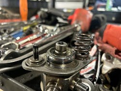
Another phone call to the shop, and an approval from the customer meant the pumps were on the way. I took all the under coverings, starter, and fuel lines out. I then popped out the pumps to find one that looked OK, but the other one came out without the spring and piston (Figure 7). There’s the fuel issue. I fished out all the broken parts and installed the new pumps.
But Wait, There’s More
Once filled with fresh oil and a filter, I was able to start the vehicle. It started right up and ran relatively well. There was a ton of white smoke coming out of the exhaust due to all the old fuel burning off. After all the smoke cleared (pun intended), I checked the codes again. There were codes for misfires on cylinders 4, 5, and 6, and cam correlation codes (the same ones it came in with) (Figure 8). All signs pointed to the timing being off on one bank. I let the shop owner know where we were at, and he asked me to prove the timing was off.
I usually like to do this the easy way: cam/crank correlation, but I decided to get fancy and use an in-cylinder pressure transducer. My plan was to take a capture on each bank and overlay them. An in-cylinder pressure waveform, in my opinion, can be the best way to visualize individual valve events without taking anything apart. I am not a guru at this, I leave the high-end deciphering work to my friend Brandon Steckler. However, I was always good at playing “one of these things is not like the other.” We hooked the in-cylinder transducer up, saved the captures, and I put them in an overlay program (Figure 9). You can clearly see that there is a difference from side to side.
Let’s Dock This Ship
What is off and by how much? I’m going to let you in on a secret; it doesn’t matter in this case. Does knowing that the intake cam is off 33.67893245 degrees change the fact that this brand-new chain will have to be reset? Nope. My diagnostic urge has been fulfilled and I am now able to report the final findings to the customer.
Could the hydro-locked engine have caused the chain to jump? Maybe. The bank causing the code was on the same side as the completely full cylinder. This vehicle had the engine so diluted with fuel that it may have caused the tensioners not to hold pressure and allow the chain to jump. Could the chain not have been set up correctly at all? Again, maybe. There is no way to prove that. When I was at the rebuilder’s shop originally, I asked if they used the proper tools to assemble the chain, and they responded that they did. I have no reason to doubt them. I can only speak to where the diagnosis led me.
I reported my findings to the shop owner, and he relayed them to the vehicle owner. The vehicle owner was done with the vehicle at this point — he was probably mad at himself for not taking it to his friend from the beginning. He asked that we put the vehicle back together and he was going to call it a loss and trade the vehicle in for something less troublesome and complicated. We reassembled the vehicle and drove it back to the repair shop, and aside from the flashing check engine light, it didn’t drive half bad.
Is there a moral to this story? I don’t know. I can tell you that I trust my diagnostic process. When I had to make a call — no matter how bizarre and unbelievable it was — I felt confident.
I can relay that to you, build your process — trust your process. Don’t deviate even though something may be unbelievable. These vehicles are only machines and follow simple rules when broken down to their base systems. Don’t discount the human factor; humans are fallible and can really mess things up whether we want to or not. And sometimes, after all this, you will have a good story to tell for years to come.
Tools used
- Scan tool
- Socket
- In-cylinder pressure transducer
- Diagrams
About the Author
Chris Martino
Chris Martino is a member of Trained By Techs and co-owner of ADAS LI, and ADAS diagnosis, calibration and programming solutions provider on Long Island, NY. He spends his days analyzing challenging and problematic vehicles and spends his evenings working to better the automotive service industry with his fellow Trained by Techs members. His specialty is electrical fault diagnosis using advanced efficient troubleshooting techniques but with a focus on the basics.
