The integration of advanced electric motor technology is a key component of the constantly changing automotive sector. Encoder motors and their close cousin smart motors are two devices that are playing a significant role in how vehicles are being designed. These advanced Direct Current (DC) electric motors are now rooted into many parts of vehicle platforms. And they are playing a crucial role in the overall functionality and sophistication of modern vehicles. (There are Alternating Current (AC) encoder and smart motors, but for this article we are going to focus on the DC type.)
Encoder motors and smart motors are not just conveniences anymore; they are requirements, because they deliver functionalities that customers now expect. The encoder motor has typically been used for convenience systems such as opening sliding doors and changing heating, ventilation, and air conditioning (HVAC) system settings, but that doesn’t mean it isn’t being used elsewhere. Today’s encoder motors offer accurate action with systems relying on their ability to provide precise motor operational information.
Many encoder motor systems will now change or vary the speed of the encoder motor as the operation is being performed. Take for example the power window operation on a BMW. When the driver or passenger touches the window switch to put the window down, the power window motor will start to move slowly, then accelerate until it approaches fully open, and then it will slow down, for smooth, efficient, and quiet operation. The same thing will happen if the request is to raise the window. Many rear power liftgates are doing this as well, thanks to encoder motors.
The encoder motor's operation can be modified by the customer and the customer’s operation characteristics can be set into the controller. This will allow the customer to set the opening height on a power rear hatch for example. The encoder motor system controller will remember the exact position that the DC motor needs to move to, opening the rear liftgate to the desired opening height that the customer has set into the system.
All these characteristics make the encoder motor and its systems so valuable on today’s vehicles, but like all systems that are on today’s vehicles, they do have issues and will need to be diagnosed at some point in time. Techs working on these systems need to understand how the system operates, what components are involved and its operating strategies before diagnosing them.
The Fundamentals of Encoder Motors
An encoder motor requires three essential parts to operate properly: a DC motor, an encoder, and the controller.
The DC motor, which may be brushed or brushless depending on the application, will be powered by 12 volts. This 12V DC motor will provide the needed mechanical power to operate the system that is being controlled. DC motors provide high torque at low speed and are reliable and efficient.
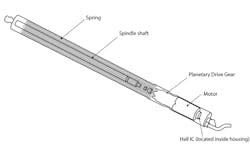
The encoder is the electrical component that tracks the DC motor’s shaft location, rotational speed, and direction of movement. It is normally mounted onto or attached to the DC motor shaft.
There are a variety of methods that can be used by the encoder to detect the movement of the DC motor. Hall-Effect, magnetic, optical and other forms of motor shaft movement detection can be used. Once the encoder has detected the motor movement it will transmit this information via digital/electrical signals to the controller which can understand and interpret these signals. This enables the encoder to function in a closed loop system and allows for precise motor positioning.
The controller is the last component directly involved in the encoder motor system. The controller will control the DC motor operation and receive feedback on DC motor operation from the encoder. The encoder motor controller will also receive operational commands either via direct human input in the form of a switch or from another vehicle module or networked module that wants the controlled encoder motor assembly to perform the desired task.
The encoder motor controller may be incorporated into the encoder motor assembly itself, but it is typically remotely located and wired to the DC motor/encoder assembly. This allows for a more compact DC motor/encoder assembly. The DC motor assembly cannot function without the controller.
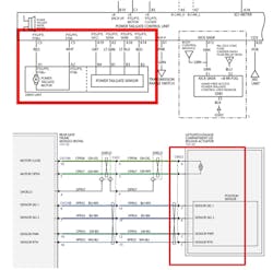
The remotely mounted encoder motor controller will use six wires to connect to the DC motor/encoder assembly. (If the encoder motor controller is incorporated into the DC motor/encoder assembly, the six connections will still be used but may not be visible).
The encoder motor controller will supply the needed voltage and ground for the DC motor to operate. It will reverse these circuits to change the DC motor’s direction. The encoder motor controller will provide power and ground to the encoder assembly for it to function, and finally there will be a pair of wires that will report the encoder signals. These encoder signal wires will provide the DC motor shaft position, rotational speed and rotation direction information back to the controller. This information feedback loop is used to control the DC motor operation, as the encoder provides real-time data back to the controller. The encoder motor controller usually contains a solid-state circuit breaker, to protect the controller and the DC motor.
The Smart Encoder Motor
Most, but not all of today’s DC encoder motor controllers will incorporate the needed circuitry that will monitor the amount of current the controller is supplying to the DC motor. This current monitoring allows the controller to modify the DC motor’s operation. If the DC encoder motor controller is capable of this and can modify the DC motor’s operation, it is commonly referred to as a smart DC encoder motor assembly.
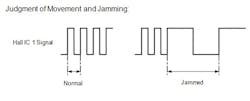
Because the smart motor controller can interpret the current that the DC motor is using, pinch or jam protection can now be incorporated into the system. If the controller senses a surge in current, that could mean a pinch or jam situation, and the controller can react by reversing the DC motor operation. This type of safety is what has turned the simple DC encoder motor assembly into a smart DC encoder motor assembly. These smart motors are now very commonly used in many systems, from power windows, power sunroofs, power sliding doors and power rear liftgates. Many manufacturers are still incorporating auxiliary pinch detection methods, such as compression or pinch sensors that change resistance if a pinch is detected.
Now that we have a firm grasp on the operation of encoder motors and their function, it is necessary to turn our attention to the management and monitoring of these systems in today’s vehicles. Let's examine some common issues, emphasizing the critical procedures for initializing encoder motor systems and the diagnostics employed to keep them reliable.
Initializations and Diagnostics
Most encoder motor controllers will generally need to be initialized before proper operation of the system. This initialization will set the operating parameters in the controller. The encoder motor controller will memorize many different pieces of data that it will acquire from the encoder located on the DC motor. The data may include motor position, motor load fully open and fully closed and other key pieces of information needed for the system to function. And they are learned by the controller during this initialization.
Remember that if a battery is discharged or replaced on a vehicle, many of these encoder motor systems will need to be initialized for them to function properly.
Diagnostics of these systems will involve the use of up-to-date information systems, often a scan tool, DVOM and the vehicle owner’s manual. Most manufacturers provide all of their owner's manuals online for free.
The owner’s manual can be a great resource of information when dealing with many of these systems, such as customer preferred settings and explaining operational characteristics.
Testing the circuits involved with an encoder motor is straight forward. Continuity testing of the wiring linking the DC motor, encoder, encoder signal wires, testing for power and ground to the encoder and DC motor is often the first step in diagnosing an issue. Testing communications networks, power and ground and switch operation to the encoder motor controller, are all typically routine tests for techs.
Most manufacturers do not provide any details or information on the encoder signals, but Toyota does provide details. The Toyota encoder uses two Hall-Effect sensors, producing square waves, that can be tested. Honda even provides instructions on how to power the DC motor, during a diagnostic if needed.
If the customer brings in a vehicle with a concern on an encoder motor system, the first step should almost always be to clear the learned positions and initialize the system again. Clearing the learned positions and other system values is often as easy as a battery disconnect, but using a scan tool is the best bet, if the system is available on the scan tool, as it will only clear the values in the system of concern.
A scan tool will often be used for diagnostics, gathering Diagnostic Trouble Codes (DTCs) and looking at the systems data, but there are a few situations where a scan tool won’t help, or can’t see the system being tested, because it’s not on any vehicle network.
The sunroof on pre-2019 GMC pickup trucks is a perfect example of this. The sunroof on these trucks uses a smart encoder motor for operation. The smart motor will prevent pinching or obstruction/blockage during sunroof operation, and fully open or fully close the sunroof automatically. But if the battery is disconnected or has gone dead, the sunroof may operate erratically. But there is another scenario that can cause the automatic opening and closing function to stop working properly. The sunroof on these trucks could have sensed a pinch or jamming event three times (updated to seven events on 2020 and newer) and that will force the sunroof into fully manual operation, until it is reinitialized.
The normal diagnostics in most techs’ minds would be to install a scan tool and look for data or DTCs, but these trucks (pre 2019) don’t have the sunroof linked to any of the vehicle networks. There are no DTCs that can be read and no data that can be looked at, so the first step in diagnostics is re-initialization.
Initialize the sunroof on these trucks is as follows:
- Turn the ignition to ON.
- Completely close the sunroof window using the close switch.
- Press and hold the sunroof vent switch to the vent open position until the sunroof window stops in vent location.
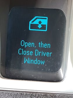
- After the sunroof reaches the vent position, release the vent switch and press and hold the vent switch again for approximately 10 seconds. Watch for the rear edge of the sunroof mechanism to move, after the movement ends, the Initialization/Teach Process is complete. Verify the operation of the sunroof in all positions.
2019 and newer GM and Chevrolet pickup trucks are now linked to the Body Control Computer and will provide some data and DTCs.
Another GM sunroof/sunshade issue could be an inoperative sunroof and/or sunshade found on some 2018-2020 Equinox and Terrain models. The inoperative condition may be the result of the sunroof controller losing its initialization. Before replacing any parts or making any repairs to the sunroof, perform the sunroof/sunshade motor actuator initialization process using the sunroof/sunshade open and close switches. Be aware that you can set DTCs on this system if the sunroof or sunshade switch is held for more than 10 seconds after the glass or sunshade has completed its initialization. Holding the switch too long can set a “stuck switch” fault code. The sunroof must be initialized before the sunshade.
The 2016 Nissan Rogue automatic liftgate is another system that is sensitive to losing its initialization. The liftgate may partially open, then reverse and close when the key fob or open button on the dash is pushed. The liftgate will function manually. Typically, B2426 and B2427 DTCs for left and right spindle sensors are set in the BCM. The Nissan systems will use two liftgate motors, one on each side.
This system may lose its calibration for several reasons:
- Manually opening the back door aggressively to the fully open position.
- While opening the back door, a wind gust pushes the door open, as the door stops at the fully open position.
- With the back door open, the side of the door is heavily bumped.
- Performing adjustment to the door hinges or striker.
There is a Nissan TSB to address this situation on most of its SUVs that have a power liftgate. Nissan wants the tech to perform initialization setting of “Automatic Back Door Position” information. This will involve a scan tool to clear the DTCs and then perform the “Reset Auto Back Door” to reset the initialization on the liftgate. After that, again with the scan tool, select “Restart” and then open the liftgate using the key fob button or the dash switch. The liftgate will open at half speed and when you hear the two long beeps the initialization is completed. After this the customer preferred height will still have to be set.
Honda tailgate systems only use one liftgate motor, on the driver’s side, and a regular gas strut on the passenger side. The power tailgate module will vary opening and closing speeds in response to the tailgate door position. The module knows the tailgate speed and position from the information provided by the pulse signals generated by the pulse sensor. (Honda refers to the encoder as a pulse generator.) There is also a warning beeper, in the power tailgate module that will provide warning sounds for various situations that the tailgate may experience. Closing and opening liftgate operation generates one specific tone, but there are seven different tones the system can emit, pointing the tech in a diagnostic direction. The Honda system also has a “Stop and Hold” function. If a button or switch is pushed during liftgate operation, it will stop and hold the position until activated again. If the Honda liftgate system senses or detects any issues in the sensors, switches or even the control unit, the unit will stop all automatic functions. Honda provides detailed tests for the liftgate components, even the encoder motor and provides many liftgate DTCs to aid in diagnostics.
Honda initialization is straightforward and is an easy system to reset or rehome after a battery disconnect, part replacement, or other issue that has stopped automatic opening and closing. To reset the Honda power tailgate manually, open it fully and then manually close it fully. After that verify that the tailgate functions normally and automatically.
The integration of encoder motors and smart motor technology into today’s vehicles is essential for enhancing functionality, safety, and overall efficiency. These advanced encoder/smart motor systems offer precise control, adaptability, and the ability for consumers to personalize various settings, significantly impacting a wide range of vehicle functions.
