The essential guide to hybrid motor generators and high voltage system maintenance
The hybrid motor generator, also known as the Motor Generator Unit (MGU), is a vital component in modern hybrid vehicles, serving as both an electric motor and a generator. This dual-purpose design allows it to provide additional power to drive the vehicle and capture energy that would otherwise be wasted, such as during braking when it converts kinetic energy into electricity to recharge the high-voltage battery. This continuous switching between motor and generator function enhances fuel efficiency, reduces emissions, and extends battery life. However, over time, the motor generator can experience issues that may reduce its efficiency or, in extreme cases, make the vehicle inoperable. The seamless operation of the MGU, whether capturing free energy during coasting or using electrical power from the battery to drive the wheels, is crucial for maximizing energy use and ensuring optimal performance across varying driving conditions.
Today's technicians must understand the design of hybrid motor generator systems and be able to identify malfunctions, such as unusual sounds, reduced performance, diagnostic trouble codes, along with warning lights or messages activated by the vehicle's diagnostic system.
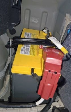
Every hybrid vehicle will still depend on a low-voltage, 12-volt system for all functionality except running the primary electric drive motors. While most technicians will concentrate on the state of the main high-voltage (HV) battery pack, the 12V battery can also fail, and this can easily be overlooked. If the low-voltage system has any issues, the vehicle can basically be disabled: doors might not unlock, onboard computer systems may not function, and — more importantly — the main HV battery won't charge. Proper inspection of the low-voltage system for proper voltage, current supply and clean tight connections is imperative and cannot be overlooked.
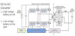
The DC-to-DC converter, or DC power control module, replaces the traditional alternator in hybrid vehicles. It manages energy transfer between the high- and low-voltage systems, charging the 12-volt battery, powering auxiliary systems, and may provide the 5-volt reference voltage needed by various sensors. The converter typically steps down the high-voltage DC, which ranges from 200-300 volts (with newer plug-in hybrids reaching 400 volts or higher, and high-performance systems exceeding 600 volts), to a steady 14.5 volts for the vehicle’s low-voltage system. These converters can deliver up to 160 amps of 12V DC power.
The DC-to DC converter’s core part is a stepdown transformer. The primary transformer coil typically connects to four PNP transistors on the high-voltage bus, while the secondary coil (low voltage) links to diodes, a serial capacitor and an inductor. The converter’s low voltage output of 12 to 14.5 volts is reached at the junction between the capacitor and inductor, with the capacitor’s negative side being grounded. The transformer's high-voltage coil is pulsed by the power transistors, altering the magnetic field and creating a voltage in the transformer's lower-voltage coil windings. The circuit's voltage and frequency are controlled and limited in part by the diodes and capacitors under the commands of the DC-to DC converter module.
Typically, the DC-to DC module only supplies low voltage output during normal ignition “on” operation or while in driving mode. But on some systems the DC-to DC converter may be functional when the vehicle is charging or plugged into a wall outlet.
A digital multimeter (DMM) and cables with a CAT III rating are needed to test, diagnose or take voltage readings to diagnose a DC-to-DC converter system.
NOTE: With all high-voltage systems, which are usually identified by orange wiring, it is particularly important to follow the safety instructions provided by the manufacturer.
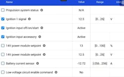
There are other important items to note while working with DC-to-DC converters. Never splice/tap into or use the DC-to-DC converter power or ground lines for other circuits/devices. Make sure that air can flow over the heat sink, and never use the heat sink as a ground for meters, scopes, or other tools. A scan tool can help you figure out what's wrong with the DC-to-DC converter by looking at current or saved trouble codes and examining the provided system data. Some manufacturers recommend using a carbon pile tester with an ammeter to test the DC-to-DC converter module output. The carbon pile tester will be attached to the 12-volt battery for this testing. The carbon pile tester will create the load on the system to see if the DC-to-DC converter can supply the needed power. Using the carbon pile tester and a capable scan tool, techs can look at the DC-to-DC converter module voltage and current output data. The ammeter reading on the carbon pile should closely match the DC-to-DC converter module current output reading, and the voltage should remain between 12.6-15.5 volts. If your shop doesn’t have a carbon pile tester, DC-to-DC converter testing can often be done with bidirectional scan tool testing. The scanner can command the set charging voltage, and the tech can see the changes in voltage as the scanner commands these changes. Be sure to allow a few seconds between voltage setting changes for the battery voltage to stabilize before changing sets points.
There have been two primary types of MGUs used in hybrid vehicles:
- Permanent Magnet Synchronous Motors (PMSMs): PMSMs are widely used in modern hybrids because of their high efficiency, power density, and consistent performance across a range of speeds. They rely on permanent magnets for excitation, allowing for a high-power factor and excellent torque at low speeds, making them ideal for city driving and hybrid efficiency.
- AC Induction Motors (IMs): AC induction motors were used in earlier hybrid models and some high-performance hybrids. Induction motors are robust and can deliver smooth power without requiring magnets. However, they typically operate with a lower power factor and are less efficient than PMSMs. Due to these factors, many manufacturers have shifted to PMSMs for most hybrid applications.
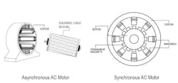
PMSMs are known for their high starting torque and are commonly found in hybrids by Toyota, Ford, Kia, Hyundai, Audi, Honda, and other brands. The PMSM MGU use permanent magnets embedded in the rotor, which help produce smooth torque and high-power density. PMSMs operate at a speed precisely aligned with the AC supply frequency. Because the PMSMs use a permanent magnet rotor, these motors synchronize perfectly with the magnetic field in the stator, without slip. PMSMs are highly efficient, particularly at low speeds, making them well-suited for city and urban driving. Their efficiency improves fuel economy and performance, while their ability to fine-tune the power factor through varying excitation enhances their versatility in hybrid vehicle powertrains. The power factor of a hybrid MGU refers to the ratio of real power (useful power) to apparent power (total power) in the system. It is an important measure of how effectively the electrical power is being used, with a power factor closer to 1 indicating more efficient power usage.
For hybrid MGUs, the power factor typically ranges from 0.8 to 1, depending on the design and operating conditions. PMSMs often exceed a power factor of 0.9 and that is why they are often favored in both hybrid and electric vehicles.
The first-generation GM Volt hybrid used an AC Induction Motor. Unlike PMSMs, AC Induction Motors don’t rely on permanent magnets; instead, they generate a magnetic field in the rotor through induction, like a transformer. In the AC induction motor, the stator serves as the primary side and the rotor as the secondary. Induction motors are asynchronous motors and run at a speed that does not directly match the frequency of the electrical current running through its stator windings. This slight mismatch, or "slip," between the motor’s speed and the current frequency is what sets asynchronous motors apart from synchronous motors. This slight slip between the rotor and the stator’s magnetic field makes the asynchronous induction motor well-suited for high-speed applications. AC Induction motors are known for their durability, cheaper cost to produce and robust performance, even though these motors may not be as efficient as PMSMs.
Both types of MGUs have unique advantages, but PMSMs have become the standard due to their superior efficiency, especially as hybrid technology has evolved.
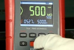
MGU testing will involve using a scan tool for diagnostics, to check parameters sensor operation, data and DTCs. If there are DTCs that direct us to test the MGU stator and its three phases (U, V, W), it can be specifically tested for insulation and conductivity faults. To check the insulation of the stator windings and cables, the Megohmmeter is needed. This special tester will send a specified voltage into the circuit during testing (special attention to proper POE and safety is needed) and most manufacturers will provide specifications. Hyundai provides a specification of greater than 10 megaohms (abbreviated MΩ), when testing the insulation of the stator windings. (Note: 1 megaohm equals 1,000,000 ohms.)
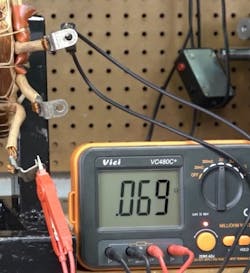
To test the resistance of the stator’s three phases another special piece of test equipment is going to be needed: the highly accurate Milliohm Meter. This meter will be needed to ensure that the resistance values of each leg are approximately the same and within specifications, and it can also be used to check the HV cables and connections. A conventional Digital Multi Meter (DMM) cannot measure the small resistance values that verify that electrical connections are clean and properly tightened. The Milliohm Meter measures the resistance in the 1/1000th of an ohm (1 mΩ = 0.001Ω. Note the lowercased m).
When testing the stator windings, we typically would be checking the resistance of the three phases, between each inter-phase winding connector (U–V, V–W, and W–U), as directed by the diagnostics. Toyota provides a specification of below 135mΩ at 68 degrees Fahrenheit with no more than 2.0mΩ difference between stator legs.
For example, when testing a stator on a Toyota Prius MGU, the following would be good test results with the tests being performed at 68 F:
Stator Resistance Measurements:
- U to V 129.1 mΩ
- V to W 128.9 mΩ
- W to U 128.8 mΩ
Calculated Differences: the resistance difference between phases is measured to figure out if there is an interphase short. This could be a copper-to-copper short.
- (U to V) – (V to W): calculated difference = 0.2 mΩ
- (V to W) – (W to U): calculated difference = 0.1 mΩ
- (W to U) – (U to V): calculated difference = -0.3 mΩ
All calculated differences are below 2 mΩ (i.e., the difference between the highest and lowest measurements should be less than 2.0 mΩ). In this example, the vehicle passes for both specifications (below 135 mΩ) as well as for difference calculation (‘Standard resistance’) between phases of MGU. (All ‘standard resistances’ are close and well below 2 mΩ).
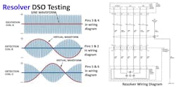
In a hybrid engine, the resolver acts as a rotary transformer that provides essential information on the motor's position, speed, and rotation direction. It has a rotor with a reference coil and two stator coils positioned at right angles. When the reference coil is powered, it creates voltages in the stator coils that change with the rotor’s angle, allowing the system to measure its exact position. An excitation circuit supplies a signal at 10kHz, 12kHz, or 15kHz to power the resolver. As the rotor spins, changes in the air gap between the rotor and stator alter the signal, which a resolver-to-digital circuit then reads to calculate the angular position. Three separate coils are used in the resolver. They are typically labeled A-B-C or Excitation (A), Cosine (B) and Sine (C) in wiring diagrams. These three coils will be used for distinct rotor information detection. Coil A will be used for rotor speed detection, Coil B will be used for detecting the rotor position, and Coil C will be used to detect the rotor direction of rotation. Scope testing is often the best method to test these circuits and there are special tools and learning procedures that need to be followed if a resolver sensor is to be replaced.
A DC-to-AC inverter is responsible for converting high-voltage DC from the vehicle’s HV batteries into three-phase AC, which will power both the PMSM and AC induction motors. The DC-to-AC inverter operates under the control of the vehicle's Electronic Control Module (ECM) or Hybrid Electric Vehicle (HEV) management module. It will use six insulated-gate bipolar transistors (IGBTs) to regulate current flow. The IGBTs direct current from the battery to the stator windings, energizing the stator coils to create a magnetic field that drives the rotor, ultimately powering the wheels. Some hybrids may use a boost converter. The boost converter on some Toyota hybrids, such as the second and third-generation Prius, is essential for stepping up and down voltage levels to improve motor performance and battery charging. Primarily, the boost converter raises the HV battery's nominal DC voltage of 144V to a maximum of 520V when needed, enhancing motor efficiency and extending the motor’s RPM range. Conversely, it can also reduce the motor generator’s output voltage to match the requirements of the HV battery, allowing efficient energy storage during regenerative braking or power generation.
In addition to powering the vehicle's AC motors, the DC-to-AC inverter can also convert the alternating current generated by the motor generators back into DC to recharge the HV batteries. Each IGBT in the system has a parallel diode between the collector and emitter, forming a rectifier bridge. During regenerative braking, this bridge converts AC from the motor into pulsating DC to recharge the high-voltage battery. When the vehicle slows down, the ECM or HEV management module will turn off the IGBTs, allowing the rotating crankshaft to turn the rotor in the electric motor, inducing AC voltage in the stator coils. The six diodes then rectify this AC into DC to recharge the battery. Regenerative braking further helps by making the motor function as a generator, creating a driveline load that slows the vehicle while recharging the battery pack, with braking force being smoothly blended by the drive motor inverter and brake control modules.
The vehicle's ECM or HEV management module will continuously check the DC-to-AC inverter's current sensors to find any sensor malfunctions. Potential issues could include a faulty inverter/converter module, failed IGBTs, an open or shorted harness, or a poor electrical connection within the assembly's circuit. Some hybrids offer the ability to evaluate the IGBTs using the Megohmmeter to measure resistance. Certain Toyota models provide an accessible cover over the IGBTs for testing. When assessing an IGBT on a Prius, a good IGBT will test between 18-19 megaohms. Anything more than 19 megaohms is considered defective.
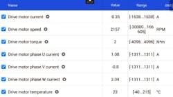
The ECM or HEV management module will also keep track of the current in each phase of the MGU’s stators, to spot any issues. Since the motor generator’s phase circuits are connected, each phase should carry a similar amount of current. The ECM or HEV/EV management module uses calculations to check the accuracy of the phase current sensors. If the sensors for the U-V-W phases show similar current values, the total difference in current flow between phases should be close to zero. If there’s a significant difference in these values, a diagnostic trouble code (DTC) will be triggered.
The ECM or HEV management module will also be looking at the temperature of the drive motor, DC-to-DC converter, DC-to-AC inverter, and other components. These sensors can generate DTCs and in some cases can be serviced. But if the drive motor temperature sensor goes bad or is damaged on a 2018 Toyota Highlander, the entire assembly (traction motor/transaxle assembly) needs to be replaced as it is not serviceable separately.
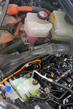
Maintaining today’s hybrid systems requires regular checks and specialized care for the best performance and longevity. The cooling system, which includes a dedicated circuit for high-voltage components like the battery, MGU, and inverter, must be routinely inspected for coolant levels, leaks, and flushed as recommended. Since hybrid cooling often uses a non-conductive coolant to protect sensitive electronics, using the correct coolant is essential to prevent overheating and costly repairs.
The lubricating system also plays a critical role in hybrid performance, with specialized lubricants needed to handle high temperatures and start-stop cycles typical in hybrid powertrains. Regular oil level checks, fluid cleanliness, and adherence to recommended oil change intervals help reduce wear on electric motors and mechanical parts.
In summary, the hybrid motor generator, along with its associated systems and components like the DC-to-DC converter and the DC-to-AC inverter, plays a pivotal role in modern hybrid vehicles. By providing dual functionality as both a motor and generator, it enhances efficiency, reduces emissions, and improves energy management. Understanding and maintaining these systems is essential for technicians aiming to ensure the reliability and performance of hybrid vehicles. From routine diagnostics to specialized testing for components like PMSMs and AC induction motors, thorough knowledge and the proper use of tools are vital for efficient repairs. As hybrid technology continues to evolve, staying up to date with these complex systems will empower technicians to provide better service and keep these advanced vehicles running smoothly and efficiently on the road.
About the Author

Jeff Taylor
Jeff Taylor is a seasoned professional at CARS Inc. in Oshawa with 40 years in the automotive industry. As a skilled technical writer and training developer, he holds licenses in both automotive and heavy-duty vehicle repair. Jeff excels in TAC support, technical training, troubleshooting, and shaping the future of automotive expertise.
