Cylinder bore distortion: Why it occurs and how to improve it
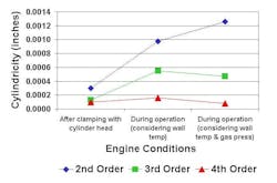
While your shop likely does not handle intensive engine rebuilds and related machine shop work, here we’ll discuss the topic of cylinder bore distortion and how this occurs. It may come as a surprise to many, but cylinder bores do not remain perfectly cylindrical during engine operation, due to operating heat, cylinder block integrity and the clamping forces that the block experiences when the cylinder head is clamped to the deck.
Is an attempt to optimize cylinder bore geometry vital for the average customer’s engine really necessary? No. Regardless, understanding this subject simply adds to your knowledge base.
Even with the best of intentions and preparation, some degree of cylinder bore distortion is likely to occur under dynamic stress (heat and pressure). The challenge is to understand how these changes take place and to establish procedures that will minimize these changes.
As the block ages and/or is exposed to thermal changes, the casting’s molecular structure will change, however slightly, which will affect bore geometry. In addition, distinct changes in bore shape will take place as the block is assembled. The clamping forces that result from the installation of cylinder heads will, in most cases, cause the bores to slightly distort as the cylinder head bolt clamping forces pull and squeeze metal adjacent to the bores. Sometimes these changes are insignificant, while in other situations, the change can be so dramatic as to cause measurable ring dragging and subsequent loss of power, fuel economy and sealing due to both out-of-roundness and frictional heat. In other engines, these problems may be compounded if the specific block is severely affected by additional distortion that results from clamping forces caused by bellhousing bolts, water pump bolts, motor mount bolts, etc.
Granted, only the more severe cases will be a cause of concern on a street engine. However, if the goal is to produce an extremely efficient engine, every factor which can affect dynamic ring shape must be considered.
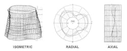
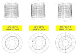
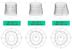
In order to accurately “map” a cylinder bore to obtain a clear dimensional picture of how that bore is shaped from top to bottom, a special “PAT” gauge is used in sophisticated engineering test labs. This is an inclinometer that features a shaft and probe. The shaft is affixed to the deck or torque plate and runs vertically through the bore centerline. The probe runs along the shaft vertically and monitors the bore walls radially. This provides a dimensional perspective view of the entire bore, relative to the theoretical bore centerline. These testing systems are extremely expensive and are typically used by piston ring and honing equipment manufacturers for analysis applications. This allows plotting the actual shape of the bore in addition to bore diameter. The readings can be displayed radially (viewing the bore from overhead) to show where the bore shifts from the centerline; and in an isometric view (side angle perspective in a variety of view angles) that allows you to see the entire bore in a dimensional manner.
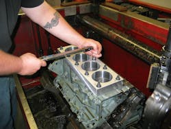
In order to obtain bore diameter readings in a machine shop without the use of this sophisticated equipment, the cylinder walls can be measured with a bore gauge at four different levels at four clock positions (12, 3, 6 and 9 o’clock). Once these numbers have been recorded, place a honing plate (one per deck) on the block, torque the plate(s) to specification, and re-measure the same points to reveal differences that have occurred. However, bear in mind that this will not reveal concentric bore diameter shifts relative to the centerline.
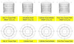
Another variable relating to bore distortion is the cylinder head itself. After measuring the bores (accessing from the bottom of the bores) on a relaxed block (no heads or torque plate), install and torque a cylinder head, and read the bores again from the bottom of the bore to note the changes that have taken place. Next, remove that head and install a different head of the same type and measure the bores once again. If you find a different distortion level/pattern, don’t be surprised. Depending on the makeup of the cylinder head, the clamping forces may reveal a different situation due to the structure of the head, especially on cast heads, due to differences in the hard/soft internal makeup of the casting core. If the head pulls down harder or softer in various areas, this will accordingly affect how the block is stressed, resulting in variations of cylinder bore shape.
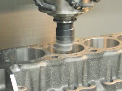
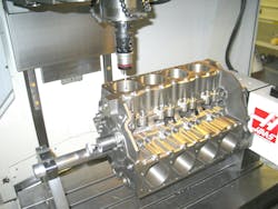
As mentioned earlier, when measuring a bore for shape, we need to remember that, depending on the instrumentation being used, we may or may not obtain a true bore shape. If we use a bore gauge, we are simply measuring bore diameter (and out of round) in specific height levels of the bore, but since we are not referencing from the true bore centerline, we may be overlooking shifts of the centerline at various height locations. If in doubt, or if we know that the radius of the bore has shifted relative to the centerline, we can use a precision bore-truing fixture to correct the problem (such as those offered by BHJ, CWT, etc.), or take advantage of CNC technology in order to establish a “new” bore centerline based on blueprint data from the block manufacturer. The bores can then be “clean-bored” to an oversize, with the cutters referenced from a fixed (and presumably correct) centerline. This will create bore trueness in a static condition, but subsequent changes may still occur when the block is subjected to loads, pressures, and temperature.
The very nature of the block casting process and the material mix can and will create differences from block to block. In other words, if you lined up five blocks with identical casting numbers and identical age, you’ll probably find five different variations of bore distortion. Knowing this, we need to temper our view of block analysis. Just because one small block Chevy of a particular series and casting shows unruly bore distortion in No. 3 bore, this does not mean that this condition will be exactly repeated in every block of that vintage and type. Each block casting is its own animal and needs to be treated as such.
Primary causes of bore distortion in relation to the cylinder head/block joint include clamping load, cylinder head gasket/combustion seal design, the honing procedure and assembly procedures.
Clamp Load
Cylinder bore distortion is directly related to cylinder head bolt clamp load. The correct clamp load is responsible for preventing the cylinder head from “lifting off", and to provide adequate compression of the head gasket to retain combustion pressure. If clamp load is insufficient, head gasket failure (combustion and fluid) is sure to result. If clamp load is excessive, the gasket may be compromised via too much crush, and cylinder bore distortion will increase.
The distribution of clamp load also affects bore distortion. If clamping loads are uneven (some bolts under or over spec), the block’s cylinder wall can easily be distorted in a random or unequal manner. It is imperative to use only new cylinder head bolts and to follow the specific thread treatment and torque (or torque plus angle) specifications recommended by the engine maker.
Cylinder Bore Honing
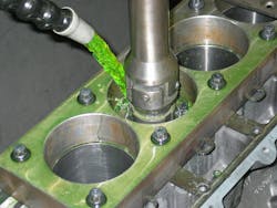
The use of a deck plate is essential when honing cylinders. A deck plate (also called a torque plate) is a machined unit that is fastened to the block to simulate the installed cylinder head. This allows you to apply the same clamping load that will occur during head installation, which will induce cylinder wall distortion. The plate is installed along with a used (already compressed) head gasket. The honing procedure can then be carried out, aiding in reducing or eliminating bore distortion. If the bores are honed without the use of a deck plate, the bores may measure with a consistent diameter, but when the head is installed, the clamping load stress will influence the bore geometry, resulting in distortion.
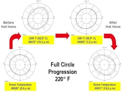
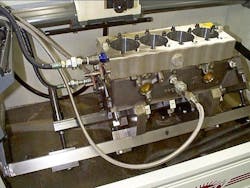
As the engine block heat changes during operation (cold to hot and hot to cold), this can and does have an effect on cylinder bore shape. In a perfect world, bore honing would take place with the block maintained at a specific range of temperature, obtained with the use of a specialized “hot honing” system, a temperature management system that most shops do not have. At the very least, simply honing with the use of deck plates will provide an advantage of minimizing bore distortion, providing improved and more consistent piston ring contact.
Head Gasket Considerations
Wire ring-style head gaskets may relax as much as 10–25% after initial assembly. By contrast, MLS gaskets relax less than 10% after initial assembly, thereby providing additional assurance of maintaining proper clamping load and load distribution.
Wire ring-style gaskets require the highest clamp load and can feature high peak loading along the cylinder openings. Again, by contrast, all active (spring function) MLS gaskets have the lowest peak loading along the cylinder openings. MLS gaskets with a built-in “stopper” layer or beaded spacer provide high combustion sealing stress with lower required bolt loading. Active MLS gaskets are designed with formed metal layers featuring contact and air spaces that work as a spring to provide compressive tension that aids in sealing while requiring lower loading. Active MLS gaskets feature an elastic element which absorbs cylinder head motion. Stopper MLS gaskets also feature a layer of “dead stop” that provides a limit to compression. Stopper-type gaskets feature rigid combustion seals which bend the cylinder head over the seal as a result of clamping loads. Active MLS offers low hardware distortion, since the gasket “gives” to reduce the chance of distorting bores and head decks. This type also provides good recovery for lightweight hardware. However, it may be difficult to generate high combustion sealing stress with an active type MLS. The stopper MLS type of gasket provides high sealing potential, but has the potential to generate high hardware distortion. Determining which type of gasket to use will be based on research data gathered during engine components, engine test assembly and engine operation (on dyno and/or on-track).
Various factors can affect cylinder bore geometry changes.
Factory original cast blocks:
- The density of the material varies
- Core thickness varies throughout
- Machining tolerances are not within acceptable performance guidelines
- Webs or reinforcement of critical areas are not optimal
- Galleys are not sized or routed optimally
- Water jackets and passages do not allow for even heat transfer
- Flow problems in molds create weakened areas
Note: While it should be obvious that addressing cylinder bore distortion is not critical for the average daily driver engine, it’s nonetheless interesting to understand this phenomenon. Addressing this and attempting to correct the condition applies to engine builders who are trying to optimize engine efficiency with the goal of minimizing parasitic drag and to obtain optimal piston ring seal.
About the Author
Mike Mavrigian
Motor Age Editor
Mike Mavrigian has written thousands of automotive technical magazine articles involving a variety of specialties, from engine building to wheel alignment, and has authored more than a dozen books that crisscross the automotive spectrum. Mike operates Birchwood Automotive, an Ohio shop that builds custom engines and performs vintage vehicle restorations. The shop also features a professional photo studio to document projects and to create images for articles and books.
