Like anything else in the world of diagnostics and driveability in particular, a sound understanding of the component's functionality is an absolute must if you want to maintain accuracy and efficiency. Why not begin with the wide-range air/fuel (WRAF) ratio sensor? After all, it’s responsible for the tight control of today’s fuel injection control systems.
The problem I have found in my years as a technical instructor and even a technician in the field is that many lessons are taught at a level that is not easily retained. What I mean is, that many lessons are delivered at a level that most technicians are not ready to receive. Now, there is nothing wrong with that, but if the idea is retention, it doesn’t work very well in my opinion. It forces memorization and that has never been a strong suit of mine, at least.
So, to bridge the gap between the intricate lessons being taught and what most technicians are capable of retaining without memorization, I will attempt to describe the WRAF’s functionality so that it simply makes sense and serves techs well where it counts the most, in the trenches.
The Zirconium-Dioxide Oxygen Sensor
To describe the WRAF in a fashion that makes sense to most technicians, I’d like to begin with the description and operation of the HO2 sensor that manufacturers have leveraged for decades, the Zirconia oxygen sensor.
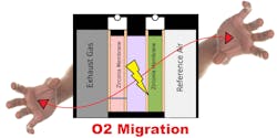
I’ll begin by saying that Zirconium possesses a characteristic that allows the sensor to be a galvanic device (meaning, it creates its own voltage). The Zirconium oxygen sensor has a Nernst cell that compares the indifference of oxygen content from the exhaust's stream to that of the atmosphere. Just like a balance scale (Figure 1). It does this through a reference chamber that is linked to the air outside the exhaust pipe. (Yes, it’s important to keep the oxygen sensor clean and free from leaking oil and such.)
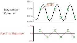
The goal of the oxygen sensor is to find equilibrium of oxygen molecules from the exhaust stream to the atmosphere (Figure 2). What I mean by that is (for example) under rich conditions, the content in the exhaust stream lacks oxygen. Under these conditions, the atmospheric oxygen content is higher than the concentration in the exhaust stream. Because the sensor seeks equilibrium, the oxygen sensor will migrate oxygen from the reference cell to the Nernst cell by pulling the external oxygen molecules through the Zirconium. As the oxygen molecules migrate through the Zirconium, a voltage potential is created (the reason we see nearly 900mV on the signal circuit under rich conditions) (Figure 3).
Now, under lean conditions, there is an abundance of oxygen in the exhaust stream. Said another way, the oxygen content in the exhaust stream is similar to the concentration in the atmospheric reference.
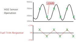
As a result, the oxygen sensor has no need for much oxygen migration (to find equilibrium) and the lack thereof creates very low voltage potential (the reason we see nearly 100mV on the signal wire during lean conditions) (Figure 4).
Limitations of the HO2 Sensor
So, now that we have simplified the functionality of the HO2 sensor, let’s focus on how that plays a role in traditional/older computerized fuel injection strategies. I’ll begin by stating an important but typically understated fact: Computers are not smart. They are simply programmed to respond to inputs, and can do so very swiftly and accurately, when functioning properly. The response is the feedback system used to maintain the operation of the catalytic converter. And to do so supports not only adequate driveability but also clean tailpipe emissions.
The HO2 sensor is just an input. It simply indicates a lack of, or abundance of oxygen (rich or lean). When the ECU sees a low voltage oxygen sensor signal (like 200mV), the ECU will increase injector pulse width to deliver more fuel. This is what we refer to as positive fuel trim. The ECU will continue to increase injector pulse width until it sees the input it desires to see: a HO2 sensor voltage increase above 450mv, the “lean/rich switch point”.
The opposite also holds true. When the ECU sees a high voltage oxygen sensor signal (like 800mV), the ECU will decrease injector pulse width through negative fuel trim. The ECU will continue to decrease the injector pulse width until it sees the input it desires to see: a HO2 sensor voltage decrease below 450mV, the “rich/lean switch point”).
Again, to maintain this tight control means to maintain a tight window around the stoichiometric air/fuel ratio of about 14.7 parts air to 1 part fuel (by weight), keeping the catalytic converter functioning. And this is where the limitation of the zirconium HO2 sensor surfaces.
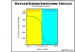
Take a look at this chart (Figure 5). Under rich conditions (a/f ratios lower than 14.7:1) the HO2 signal immediately switches to a high-voltage output. And on the lean side (a/f ratios above 14.7:1) the sensor signal immediately switches to a low-voltage output. The sensor has no ability to indicate just how rich or how lean the exhaust gas is — only if it’s richer than stoichiometry or leaner than stoichiometry. It’s for this reason we have been told for decades that a catalyst can only function at stoichiometry, and that isn’t entirely accurate.
The whole truth is ECUs can only see what the HO2 sensor shows them (rich or lean). I equate this to attempting operation of a radio-controlled airplane. So long as the plane doesn’t duck behind some trees, and I can see it, I can maintain control of it. But if it goes out of sight, I can’t maintain control. Very similarly, if the a/f ratio deviates too far away from stoichiometry in either direction, there is no way to know just how far away from stoichiometry the a/f ratio is because the HO2 sensor cannot display it (loss of fuel control and catalyst functionality).
The WRAF Ratio Sensor
So, with the increase in sensor technology comes the WRAF. In my experience, this highly sophisticated device is quite difficult for most technicians to understand in the way it's typically presented. For this reason I wish to simplify its functionality with some analogies.
I’ll begin by stating that the WRAF is like having two devices built into one unit. The traditional functioning HO2 sensor properties still exist. As the exhaust oxygen content is being sampled, the sensor will output a signal amplitude that correlates with oxygen concentration. However, the goal of the ECU is to monitor that signal and attempt to keep the signal voltage at 450mV.
The second part of this device is the Nernst cell which has an amperometric property, meaning it uses current flow to perform some work. Its job is to move oxygen molecules in and out of the Nernst cell. But I will ask that you think of this cell with an easy-to-imagine analogy.
Picture a man with a shovel. His job is to use the shovel to move oxygen molecules in and out of the Nernst cell. If the HO2 signal increases above 450mV (indicating a lack of exhaust oxygen content or rich condition) the man with the shovel will move oxygen into the Nernst cell to reduce HO2 sensor signal voltage (again, the goal is 450mV).
If the HO2 sensor signal voltage drops below 450mV (indicating an abundance of exhaust oxygen content or lean condition) the man with the shovel will move oxygen out of the Nernst cell to increase HO2 sensor signal voltage and attain the goal of 450mV.
The ECU watches the man with the shovel and its job is two-fold:
- Determine the direction the man is shoveling the oxygen molecules.
- Measure how hard he is working.
With these two primary objectives, the ECU can not only determine “rich” or “lean” (like the zirconium oxygen sensor), but can now determine “how-rich” or “how-lean” the exhaust gas is.
Data extraction
The WRAF sensor’s output to the ECU varies depending on which side of the ECU is being monitored (OBD2 global vs. enhanced data). It can be a voltage signal, a bi-directional amperage signal, or both. And to be honest, the sensor signal's amplitude means different things on different vehicles.
For instance, stoichiometry is indicated on a Honda when the sensor signal is at 2.2V, but on a Toyota at 3.3V. Then, you have Subaru whose sensor may indicate 2.5V at stoichiometry. I can understand why so many technicians get off in the weeds about these devices. It’s all very confusing.
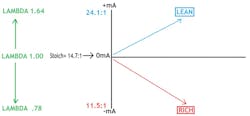
With that, I almost never look at those values. I let the computer do the work. Those values will correlate with the ECU’s programming to indicate an air/fuel ratio. I simply look at the end result — because that end-result is the same on every OBD2 certified internal combustion engine on the planet. This chart below shows the relationship of current values to Lambda and that is exactly what I’m after (Figure 6).
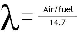
Lambda is the equation that compares the actual measured air/fuel ratio to the ideal air/fuel ratio (for the fuel being used). A lambda value of 1.00 is stoichiometry. A value exceeding that represents an abundance of oxygen and below that, a lack of oxygen. The takeaway is, it does not matter which vehicle, which fuel is being used, or which professional scan tool you are leveraging.
The chart shows exactly what the man with the shovel was telling the ECU. As the sensor detected a rich exhaust content, the amperage output as a negative value (shoveling oxygen into the Nernst cell). The harder and faster the man shoveled, the further the amperage signal deviated negatively from 0 mA (0 mA is “stoichiometry” — how convenient) (Figure 7).
The opposite holds true as well. As the sensor detected a lean exhaust content, the amperage output as positive (shoveling oxygen out of the Nernst cell). The harder and faster the man shoveled, the further the amperage signal deviated positively away from stoichiometry). If we go back to the analogical perspective, this would now be like operating a drone with an on-board camera. We can pilot it far out-of-sight and still maintain great control. The WRAF allows the ECU to accurately detect a/f ratios as lean as 24:1 and a rich as 11.5:1
In Summary
Heated exhaust gas sensor signal feedback continues to govern the operation of the computerized fuel injection system, and for the same reasons. With the increase in sensor technology and computer processing capability, the goal of the system is no longer to maintain stoichiometry and ensure catalyst functionality.
For example, if the vehicle in question suffered from the potential to produce NOx, we realize as technicians, high temperatures are the root cause of NOx production. NOx production becomes an issue in temperatures exceeding 2500 degrees Fahrenheit. If an ECU was programmed (under certain operating conditions) to create an air/fuel ratio below 14.7:1, that richer mixture will serve to quench the combustion chambers, lowering the temperature and reducing overall NOx production.
On the flip-side, there is no need for a rich mixture during light-cruise conditions because torque production is not required. If an ECU was programmed to increase the air/fuel ratio above 14.7:1 this would serve to boost fuel efficiency.
Through the eyes of the post-catalyst HO2 sensor (sometimes a post-catalyst WRAF is utilized in new vehicles) the remaining oxygen content will indicate whether the catalyst is still functioning. As long as the catalyst is doing its job, the vehicle will remain emissions-compliant.
The goal now is to monitor the operation of the catalyst and take the air/fuel ratio as far away from stoichiometry as needed to accomplish other goals. Taking the time to wrap our heads around the following is absolutely crucial to accuracy and efficiency as a technician in today’s shop:
- The functionality of the Zirconium-dioxide HO2 sensor
- The functionality of the wide-range air/fuel ratio sensor
- The strategies of both new and past ECU driven fuel injection systems
This allows anticipation during testing and the ability to capture and view preliminary scan tool data (right from the driver’s seat) so time isn’t wasted testing unnecessarily. But don’t take my word for it. Take the time to try it out for yourself and you will be glad you did!
About the Author
Brandon Steckler
Technical Editor | Motor Age
Brandon began his career in Northampton County Community College in Bethlehem, Pennsylvania, where he was a student of GM’s Automotive Service Educational program. In 2001, he graduated top of his class and earned the GM Leadership award for his efforts. He later began working as a technician at a Saturn dealership in Reading, Pennsylvania, where he quickly attained Master Technician status. He later transitioned to working with Hondas, where he aggressively worked to attain another Master Technician status.
Always having a passion for a full understanding of system/component functionality, he rapidly earned a reputation for deciphering strange failures at an efficient pace and became known as an information specialist among the staff and peers at the dealership. In search of new challenges, he transitioned away from the dealership and to the independent world, where he specialized in diagnostics and driveability.
Today, he is an instructor with both Carquest Technical Institute and Worldpac Training Institute. Along with beta testing for Automotive Test Solutions, he develops curriculum/submits case studies for educational purposes. Through Steckler Automotive Technical Services, LLC., Brandon also provides telephone and live technical support, as well as private training, for technicians all across the world.
Brandon holds ASE certifications A1-A9 as well as C1 (Service Consultant). He is certified as an Advanced Level Specialist in L1 (Advanced Engine Performance), L2 (Advanced Diesel Engine Performance), L3 (Hybrid/EV Specialist), L4 (ADAS) and xEV-Level 2 (Technician electrical safety).
He contributes weekly to Facebook automotive chat groups, has authored several books and classes, and truly enjoys traveling across the globe to help other technicians attain a level of understanding that will serve them well throughout their careers.
