Communication faults are frequently among the most difficult to solve, but when the fault is both intermittent and instantaneous, we are now talking about a whole new level of challenge. And when the customer is so upset, they wish to pursue a Lemon-Law claim, it’s time to step up to the plate — and be sure to bring your “A-Game!”
Today’s Subject Vehicle
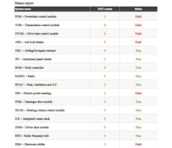
A student reached out to me with a 2014 Jeep Cherokee , as it entered his shop with the complaint of “loss of communication at times.” The diagnosis began with a scan for DTCs for each node on all the networks. Fault codes existed solely for communication faults. There were a total of ten DTCs and all of which existed only on the CAN_C network (Figure 1).
After reviewing and documenting the stored DTCs, it seemed all pertained to complaints with either the CAN bus, in general, or three specific nodes:
- ABS control unit
- Transmission control unit Power Steering control unit
Searching for the Correct Diagnostic Path
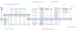
The above information led to visiting the topology of the system configuration. This layout of the entire CAN_C bus (along with the stored DTCs) helped to triangulate a likely area where the fault may lie, and more importantly, suggested an area to begin testing the CAN_C bus circuitry (Figure 2).
Now, considering the bus will support communication of the other nodes, some assumptions can be safely made. The CAN_C bus cannot be shorted to ground, shorted to voltage, or CAN_HI / CAN_LO cannot be shorted to each other. What’s more is that all suspect-nodes share the same Star Connector (a comb-like splice pack). The Star Connectors also house the terminating resistors that stabilize the bus.
The most logical approach is to view the CAN_C bus scope waveforms (live activity of the bus messages being exchanged). However, considering the nature of the fault, it’s best to capture in two different areas (at the DLC, terminals No. 6 and No. 14 and at a node downstream of the Body Star connector). The PCM was the chosen node (the inline-connector C1205, at the dash, just after the PCM, was the sample point). This is mainly due to relatively-easy access.
Assembling the Puzzle Pieces
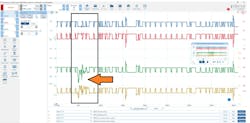
When sampling at both locations, there is a distinct difference in the paired waveforms. RED and BLUE (CAN_HI and CAN_LO, respectively) were sampled at the DLC. GREEN and YELLOW were the same circuits but sampled at the PCM (passing through the Body Star Connector).
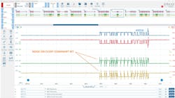
There is a visible fault present at the PCM sample point but not at the DLC (Figure 3). Scrolling further through the data, we can see another anomaly occurring similarly. However, there appears to be inductive voltage kicks visible each time a dominant-to-recessive and recessive-to-dominant bit exchange occurs (Figure 4). Could this be a clue to the nature of the fault?
The Data Doesn’t Lie
With all the information in front of us, and the desired information not yet obtained, we are faced with deciding how to proceed. Here are some bullet points of what we know to be factual, and I will ask all of you, diligent readers, for your input on what they mean to you, collectively:
- Intermittent communication faults present
- Triangulation limits the root cause to just three potential nodes sharing a star connector
- CAN_C scope captures indicate what appears as a capacitive discharge
- When fault presents, it’s during each message bit-toggle
Given this information, what would you do next?
- Replace the least expensive node first.
- Replace all nodes with stored DTCs.
- Inspect connector between PCM and CAN_C bus.
- Replace PCM because fault occurs during drive only.


