I've frequently seen this inspirational meme that states "Thomas Edison didn't fail to make the light bulb, but rather he found 10,000 ways how not to." When I think about my time as an automotive technician it is filled with some good times and a lot of real horror stories. A lot of times I am beating my head against a wall because I want to know where I went wrong in my approach. To me, a misdiagnosis has never been a pride battle. To me, a misdiagnosis means, I either wasted the customers' money or the team lost money. When that happens, I focus on my diagnostic process and where I failed. However, after all the money is down the drain, there is a silver lining, and that is that I learned something that will help me be more proficient the next time around.
There is a certain breed of technicians out there that strives to be the best in all that they do. If you are sitting reading this article on your lunch break, chances are you and I are quite alike. Most of the time for me it's not about the paycheck. Sometimes it's just about helping others and protecting their best interest. I love this quote as it's loosely attributed to Aristotle's theological beliefs, "You are what you repeatedly do, therefore excellence ought to be a habit, not an act". I do strive for excellence in my automotive career, but I often fall short. This article focuses on my responsibilities and failures as a shop foreman and a diagnostician, so you don't go down the same rabbit hole I did.
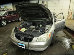
This car is new to our shop and we have no history on the vehicle other than the vehicle was just purchased. Trouble codes were pulled from the vehicle and a p0300 was present in the engine controller. This initial check out was done by my coworker Josh. We swapped once he ran into a dead end. Right from the get-go, my coworker had told me that this engine had a misfire only at idle. I told him that I highly suspected either an upper end sealing issue was present, or a vacuum leak along that cylinder's intake runner.
Early on he performed a clear flood crank and heard no cranking cadence issues. We quickly evaluated the engine with a mechanical gauge and there was no obvious issue that would indicate a mechanical failure other than sometimes the manifold vacuum was low. It didn't exhibit an obvious bouncing needle as a typical valve train problem would. We looked at scan data to look at the fuel trims and we thought we may have found something. At idle the trims were 10%. Under load, the fuel trims went to right around 0. On most engines, especially with a fuel metering oxygen sensor on each bank, those trim numbers become less significant. I want to use some basic math here to explain my statement. Take a typical v6 engine where each bank has one upstream oxygen sensor. That means a bank of 3 cylinders makes up 100% of fuel control. We can say this another way, each injector makes up 33.33% of total fuel control. If you had a no fuel misfire due to a dead injector, for instance, I expect that the fuel trims should be right around 33% for the bank with the misfire. This engine is an oddball of sorts for fuel control.
This engine has two oxygen sensors total, one downstream for catalyst monitoring, and one upstream for fuel trim metering for all 6 cylinders. If we do the math again this engine has 6 cylinders contributing to 100% of fuel control. That means that one injector contributes to about 17% total trim. We get that number by taking 100 divided by 6. If I had a vacuum leak near one cylinder's intake runner or a partially clogged injector 10% fuel trim can indicate a problem. Based on the trim numbers I had on this vehicle a smoke test and possibly an injector balance test may have been needed. Unfortunately for me, the fuel trims were just a broken PCV return hose near the intake boot. Once that was fixed the misfire was still present and trims were close to 0. Now I decided that I am going to attack mechanical testing heavily because vacuum leaks and fueling issues have been ruled out.
One of my greatest joys of being in a leadership role is that I get to teach my coworkers what I have learned. I love pushing others to be better and I also love to learn from my guys on how I can be a better foreman. True leadership, in my opinion, is not based on how good of a technician you are or how experienced you are. Leadership is about your ability to influence those you manage to be their best. In my experience lacking humility in a leadership role can prove to be unfruitful. For a long time, I struggled with the idea of leadership. My boss, Jason Brennan, saw a leader in me when I didn't believe in myself. I always thought that to be a shop foreman you needed to have an answer for every question brought about in the shop. As I grew as a diagnostician, I realized how incorrect my thinking was.
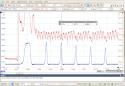
Over the years at Finetune Automotive we have routinely experienced mechanical engine problems. Sometimes I feel like we're a drivability shop because of how much work we get that pertains to it. Everyone in our shop knows what a relative compression test is and what the benefits are. Something I failed to emphasize to my guys is how long to perform this test. Should I crank the engine over for 2 seconds or 15 seconds? Earlier in the article, I talked about how my coworker performed a clear flood crank to listen to engine cadence. This car would have been diagnosed right then if two things would have been different. The first thing that hindered an accurate diagnosis was the condition of the battery. In this case, the battery was garbage. You couldn't crank this car for any period without the battery dying. The second thing is I should have emphasized to my team is that time is a great contributing factor to getting accurate results via a relative compression check.
In this capture (Figure 1), we can see that the red trace is starter current fluctuation during a cranking event. Using an inductive current clamp around the battery or starter cable I can see the impact compression has on starter motor current. These voltage fluctuations represent top dead center for each compression event. I also used an in-cylinder pressure transducer as a sync. A sync on a gasoline engine represents an ignition or peak compression event to allow the user to identify which cylinder is which. As we can see, the compression is sometimes there and sometimes not. If we would have performed a clear flood crank with a 10-second crank, we would have heard the lack of compression. The condition of the battery would not allow for this and I never emphasized that time could prove valuable to accurate testing. Now that we know we have a mechanical problem is let’s try to figure out what’s going on.
I try to do as little work as possible to determine what the problem is. Sometimes that doesn't work out in my favor. With that in mind, sometimes I'm going to use a couple of different methods to back my hypothesis. I would say I'm still new to vacuum waveform analysis. Typically, I will not back any hypothesis based on one test result. In this circumstance, I used cranking current, vacuum waveform via a homemade first look sensor and an in-cylinder pressure waveform to bring all my data together. There are certain vacuum waveforms that at first glance you can pick out patterns and associate common problems with. I don't recommend relying on patterns to drive your diagnostic path but with that in mind sometimes the problem can be obvious.
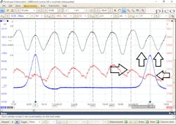
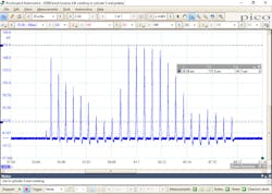
In my vacuum waveform capture (Figure 2), two cylinders have low compression. The arrows in the capture point to both the low compression and weak intake pulls. Above the two cylinders that have low compression are two vacuum pulls that are not as deep as the others. In my experience, this can likely be a leaking intake valve. The idea is simple enough, when a leak occurs at an intake valve, we have a positive pressure push in the intake manifold as the suspect cylinder approaches top dead center on the compression stroke. The intake valve should start to close shortly after bottom dead center. The amount of compression in a cylinder is primarily a function of when the intake valve closes during the compression stroke. A leaking exhaust valve will not show up in the intake manifold waveform above the suspect cylinder's low compression event. What you likely will see however is a deep pull in vacuum after the cylinder's low compression event. This has to do with the speed and rate of change in crankshaft rotation.
As you have already seen in the waveform, the pulls are not getting deeper after the low compression event. With this vacuum waveform analysis completed, I'm suspecting that the leak is at the intake valve. I want to use another technique to back up my hypothesis to make certain I'm headed in the right direction. I use an in-cylinder running/cranking compression waveform to test my hypothesis and both of those tests supported a leaking intake valve. However, when using a leak down tester it passed the test on several different occasions. My boss was stumped at how a leaking valve could pass a leak down test and I was explaining to him that dynamic testing is always best to find an intermittent problem. I explained that as the engine rotates the valves also rotate. As it rotates, it can hit an area of the seat that will not seal, and you have a leak.
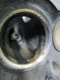
We got the approval on this job to do cylinder heads. I thought that the evidence was clear that there was an upper end sealing issue. The job was given to one of my other teammates to do the head job as I was backed up with other work. He got the heads pulled off and I wanted to take the valves out of the cylinder that I suspected the intake sealing issue to be present on. I thought I had nailed the diagnosis. Figure 3 shows that the valve is not sealing on half of the valve seat surface. The seat was also discolored and slightly pitted. We sent both heads to the machine shop and they informed us both heads were cracked near the intake seat and one of them was in need or replacement. The other head was able to be repaired. This built my confidence that we were going to fix this car.
Fast forward to a couple of weeks later the engine is back together and to my horror, it still has an idle only misfire on cylinder 5. My confidence was completely gone. I've had bad machine work before, and I was thinking to myself that the likely hood of a machine shop failing to do 3.8l heads is slim to none. Well, I wasn't wrong; they didn’t do anything incorrectly I had overlooked something big. I restarted the diagnosis and did all the tests again and then some more. I shared my captures with my colleague, Pedro De La Torre. Pedro agreed that I had diagnosed it correctly and that there is, in fact, an intake valve leaking.
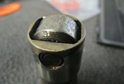
What did I miss? My boss is losing confidence in my diagnosis. I really had to convince him that we had to take the heads back off. A job no one wants to do for the second time. The heads came back off and went back to the machine shop and they checked ok. At this point, I think most of my hair fell out. I went over to the torn apart engine and we take the lifters out and inspect the camshaft. This is something I should have been aware of, but this was the first time I had seen this problem. On the 3.8l platform when the intake gaskets go bad, they leak coolant onto the cam lobes and destroy the cam. I’ve known this for years, but I didn't suspect this to be the problem. In my experience usually, it results in an intake path restriction or an exhaust path restriction when the lobe gets wiped out. In this situation, we have a leak present, not wiped out lobes. Figure 4 shows the bottom of the lifter roller. It may be hard to see from the picture, but the roller is out of round and loose. We put our thinking caps on and worked together at the shop to understand how this can cause a leak. To understand this, we need to talk about the lifter design.
The hydraulic lash adjuster has been around since the 1930s when General Motors used them in a Cadillac engine. As we have all experienced, they’re in almost all modern engines. This alleviates the need to adjust valve lash as maintenance. The lash adjuster is fed oil through the bore of the lifter via the oil gallery. This oil pumps up the pushrod seat. As oil enters the lifter body a hydraulic cushion is formed. This cushion takes up the slack in the valve train to maintain zero lash. A flat spot or faulty roller bearing will contact the lobe as the engine rotates. When this happens, momentarily lash is created in the system. Then the cushion expands via hydraulic filling to take up the clearance. As the engine continues to rotate and the flat spot loses contact with the lobe, lift is added back into the system. This extra lift that is added holds the valve open until oil can bleed back out of the lifter through spring pressure.
Looking at the in-cylinder capture in Figure 5 while cranking the engine clearly shows how cyclical the pattern becomes. This pattern is not typical of an upper end sealing issue created by pitted valves. I have seen pitted valves and it is best illustrated by a high low high low compression peak. As I look back over this scenario, I learned a lot. It is through our failures that we should reflect and grow. Up until that day I had never experienced this exact scenario. What I hope that you all take from this article is a couple of things, crank the engine over for a long time, always inspect the camshaft, be open to being wrong, and have the courage to tell your misfortunes to help others.
