As a mobile technician, when you get a call to look at a vehicle, you never know exactly what you're in for. You can visualize it in your mind, but until you arrive at the vehicle you don't know what to expect. This is what happened when I arrived at this story’s vehicle—a 2011 Chevrolet 1500 Silverado with 118,034 miles on the odometer. This vehicle looks like any other Chevrolet four-by-four pickup truck except that it's about four feet taller than a standard Chevrolet truck (Figure 1). To some of you, that's probably no big deal. I'm not the tallest person in the world, so this posed an extra challenge for me. The first order of business was to secure a stepladder, fender covers, and an area for my test equipment. I also enlisted my technician friend, Joe Green, to assist me in my diagnostic testing of this vehicle. What’s the old saying? “Many hands make light work.” I believe this to be true, especially on this vehicle.
Today’s challenge
The customer’s complaint with this vehicle was that it ran rough (“It doesn’t feel like it’s running on all cylinders and just doesn’t have the power it once had.”). The first item of business that most of you would perform is a pre-scan of all the control modules. Since this is an engine performance issue, I wanted to look at the stored diagnostic trouble codes (Figure 2). Notice that one of the codes that was stored was a P0300. As you likely know, that code indicates a random cylinder misfire was detected. The other codes of interest were a P0336 (which is a crankshaft sensor performance issue) and a P0171 - “System lean on bank one.” Unfortunately, a cylinder-specific DTC was not generated. Either of the stored DTCs—the crankshaft sensor code, or the lean code—could’ve been related to a misfire.
I like to start my diagnosis by evaluating the computer’s ability to control both the fuel delivery and the ignition system. This is easily conducted with a scan tool by evaluating some basic PIDs (parameter identification) like that of “fuel trim” found on any global diagnostic tool. I also like to see how the combustion process is carried out. To gather that information, I hooked up a five-gas engine analyzer so I could see exactly what's going on during the combustion process. Evaluating the gasses exiting the tailpipe could yield us that information. Using a five-gas analyzer can give you a lot of clues that the vehicle's control module can't. Although evaluating an engine's mechanical condition is what I typically do first, I chose this route.
Deciphering the exhaust gas content
On this particular vehicle, the exhaust system was modified into two separate tailpipes. This was good news for me, as I could take readings from both sides of the engine individually, which allowed me to quickly identify the bank housing the misfire. The firing order for this engine is 1-8-7-2-6-5-4-3, with bank one located on the driver’s side. I stuck the exhaust probe into the driver’s side tailpipe to get a reading. What’s important to analyze are the individual gas readings. I will just focus on a few of them necessary for this diagnosis (Figure 3).
Carbon monoxide (CO) is a rich indicator gas. It is present in abundance when combustion of a rich mixture occurs. The more rich the air/fuel mixture is, the higher the CO reading will be. The CO gas reading from bank one is low. That told me that this bank is not over-fueled.
The hydrocarbon reading (HC) is unburnt fuel. It’s indicating that there is some unburnt fuel detected in the exhaust gas. This may be present because the catalytic converter has not yet lit off and is not cleaning up the gasses. All engines will emit some HCs.
Next, I inserted the analyzer probe into the right bank tailpipe (bank two) to get a reading. As you can see, this reading was completely different than the other bank (Figure 4). Focusing on the HC reading, it’s indicative to me that a serious lack of combustion (or something else seriously wrong was occurring) in one of the cylinders on this bank. I didn’t focus on the other gasses as the high HC PPM (Parts Per Million) reading gave me what I needed to see that bank two housed the misfiring cylinder. It indicated a lot of unburnt fuel. That is what sent me on to my next test step.
Staying the diagnostic course
After obtaining this reading, I clearly understood that bank #2 is the one that the customer is experiencing a problem with. So, now I have to isolate which of the four bank-two cylinders is my problem cylinder. Just like in the old days, if you want to get a good idea of how each cylinder is performing, you would do a compression test. So, I brought my scope out and wanted to perform a relative compression test instead (Figure 5). This test allows me to use a current clamp for monitoring starter motor amperage. Since amperage relates to mechanical load, an increase of load will increase amperage where a decrease in load will decrease amperage. This test will give me an overall analysis of how each cylinder can load the starter motor during a compression stroke. If compression is the same from cylinder to cylinder, the load should be the same from cylinder to cylinder. If not, the suspect cylinder will be visible in this trace, indicated by a decrease in amperage during that cylinder’s top-dead-center (TDC) compression stroke. This test is a lot faster than using a mechanical compression gauge on each cylinder. Remember that time is money. By hooking up my amp clamp around the positive battery cable and another scope lead to a coil control signal circuit, I could identify if a cylinder was low on compression and which one it is.
-YELLOW= Amp Clamp
-GREEN= Cylinder #6 Coil Control Signal
The green channel would be the cylinder identification channel based on the firing order. As you can see during a “clear flood” cranking event (over ten seconds) that cylinder number six is my problem cylinder. I labeled the cylinders on the scope for reference, based on the firing order. The green ignition strike is occurring, indicating cylinder #6 is near TDC compression at that time. Because a hump is missing from the relative compression trace at the same location, it’s clear to see cylinder number six is the cylinder that has low compression and, as a result, is misfiring. This occurred over and over again as the engine was cranked over many cycles. This is what the five-gas analyzer was also telling us. Sometimes when you do testing you will perform a test and it will confirm what your previous test was showing you. Both test results point to a similar problem.
Getting to the root cause of the fault
Because of the relative compression test result, I had reason to check the mechanical condition of the cylinder. I had my technician friend Joe install a 500psi pressure transducer into the cylinder's spark plug hole so we can perform a compression test. While putting the truck in “clear flood” mode once again, I did a ten-second crank test to obtain our reading (Figure 6). As you can see, the compression is very low. It's only reading about 20psi! This confirmed what the relative compression test inferred earlier. One thing to keep in mind is when you are performing a test you always want to obtain accurate data. The in-cylinder waveform I gathered wasn’t quite the best one I could’ve retrieved. It couldn’t offer me the specific details I desired about valve opening/closing events, or cylinder leakage typically found. But it did give me enough information to determine the compression is low, and that there was a valve issue going on here. Remember—data from your testing will drive you to your next test.
Now I was at the point where we would need to disassemble part of the engine to continue further in our testing. I usually have the shop do that for me. but since Joe is here helping me, he removed the bank two (suspect bank) valve cover so we can get a visual look at what is going on with the valve train. If a cylinder can’t inhale correctly, it can affect the compression reading.
Visual confirmation of the fault
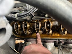
Once we had the valve cover removed, I proceeded to crank the engine in “clear flood” mode again and we could visually confirm the issue. The intake valve for the suspect cylinder was hardly moving at all, nor would it seal properly (Figure 7). We checked for a broken valve spring but it was ok. We also looked at the pushrod to see if it was bent but no problem was found. At this point in our diagnosis, it is apparent that the intake manifold and cylinder heads will need to be removed for a better visual inspection of the valve lifter and camshaft lobe. With the cylinder head removed we can also get a better look at the valve in the head to see if it's damaged in any way.
I had the shop remove the cylinder head and no problem was found with the valve. However, there was a problem with the number six intake lifter and the lobe of the camshaft that the lifter rides on. This is our culprit for our misfiring cylinder (Figure 8). I don’t know how well this vehicle was maintained nor do I have the historical records on it, but a lot of times this kind of failure is due to the engine oil breaking down and not sufficiently lubricating the camshaft or lifter.
This diagnosis wasn't a particularly hard one to do. It was successful in the fact that it was a data-driven process. By starting at a point where I could gather some good useful information, I was able to analyze it, which then allowed me to move on to my next logical test. As a mobile technician, my job is to come to a diagnostic conclusion as quickly as possible. Not only is the speed important, but the accuracy as well. However, in hindsight, I acknowledge that had I performed the relative compression test first, there would’ve been no need to perform exhaust gas analysis. Always be open to learning how to streamline your diagnostic process. This is how we improve and become more efficient. Notice that there wasn't any disassembly going on until it was justified to remove the valve cover. Even that was a minimal investment of time. Streamlining your diagnosis is the difference between a well thought-out diagnosis and a diagnosis where you're testing randomly. Having the ability to use the correct tools coupled with the knowledge and training goes a long way to a successful conclusion. Starting with the scan tool then the five-gas analyzer and finishing with the lab scope was not the most efficient, but it was the route I chose, and it made this job go much smoother than expected with no guesswork. Your steps and the order that you would take them might differ, but the correct diagnosis is the important thing.
This fault could have been properly diagnosed with a mechanical compression gauge and a cylinder leak-down gauge but, if you are like me, you too prefer to exert less work and reap bigger rewards. That’s why upgrading your diagnostic tool arsenal will help you immensely. Having my technician friend Joe Green help me made all the difference in the world. While he climbed the ladder to do the necessary hookups, I stayed on the ground and monitored the results. Using event-driven diagnostic test steps and putting together a diagnostic game plan will ensure that your troubleshooting skills will be a success.


