5 tips for making the most of your digital storage oscilloscope
So you’ve taken the plunge and decided to buy a digital storage oscilloscope (DSO). Congratulations! This is a great diagnostics asset to have in your belt. But now you may be wondering what exactly you can do with your new tool. Here are five tips so you can take full advantage of your DSO.
1. Taking a look at oxygen sensors
Scan tools are a great starting point for diagnostics. But a scope will show much greater detail and present data much more quickly than a scan tool does. For example, some scan tool systems that detect a faulty O2 sensor will substitute the values from the corresponding O2 in the opposite bank, so if you are not paying close attention, you may be fooled.
You won’t have this problem with a scope. You can even use your DSO on an O2 sensor to detect misfires or fueling problems on a specific cylinder. Connect one channel (if you have a multi-channel DSO) to your O2 sensor output and use another channel to trigger or “sync” with the spark or injector of the cylinder in question. Then, with the engine running, you should be able to see if that cylinder is running leaner or richer in relation to the other cylinders. You can also see if an injector is physically spraying more fuel than intended. Using the O2 sensor can help you see if there is a mechanical problem, something you wouldn’t be able to do if you scoped the injector trigger voltage. A scope there will show the electrical integrity of the injector, but not how much fuel is actually flowing through it.
2. Analyzing CKP and CMPs
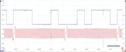
Instead of spending hours disassembling to look at a broken timing chain, simply hook up the scope to the crankshaft position sensor (CKP) and the camshaft position sensor (CMP). Now you can see the relationship between the CPK and CMP. Typically, at TDC you will see them aligned, although some manufacturers will have them off by 50 percent.
Make sure you disable variable valve timing (VVT) when doing this. If the engine does not run, you can still get a waveform during cranking. Some manufacturers publish good waveforms in the service information found in ALLDATA. If you’re unable to find them there, known good waveforms can often be found on online forums.
3. Evaluating anti-lock braking system wheel speed sensors
You can also use your DSO to evaluate the performance of an anti-lock braking system (ABS) wheel speed sensor (WSS). For example, if you have an intermittent WSS code or unintended ABS activation. Connect your scope to a WSS (or all three or four if you have a multi-channel DSO) and drive the vehicle.
You can now see if any WSS is outputting a weak signal (low amplitude/voltage), a noisy signal or if a signal is dropping out. This can point you to a particular sensor that is either mispositioned, reading off a damaged tone ring or has just failed.
4. Checking the condition of a fuel pump
What is the condition of the fuel pump? A DSO can tell you! With a clamp-on inductive amperage probe coupled with your DSO, you can look at the current waveform and check for burned commutator or brushes. You’ll see this in the roughness of the waveform. You can also go deep and calculate how fast the pump is turning or if it is drawing too much current, usually due to age or restrictions in the fuel system (i.e., a clogged fuel filter). There are many ways to accomplish this kind of testing – just connect your amperage probe anywhere in the fuel pump circuit without going near the fuel pump.
For example, you can pull the fuel pump fuse or the relay, install a jumper wire on the feed circuit and put your probe on that jumper. You can even run a test lead from B+ to the power wire to the pump at the fuse box, bypassing everything else that could be on the circuit. Use your imagination to find the simplest way to make your connections on whatever circuit you are looking at.
5. Diagnosing data activity
Network problems can be very intimidating and frustrating and “Uxxx” codes can be vague, to say the least. When working a network (serial data or CAN lines), you can connect your scope directly at the Diagnostic Link Connector (DLC) and “see” the data activity. If you want to look at the network in question, connect your scope to whichever DLC pins are used by the network you are testing. Is the voltage correct? Is there any voltage at all? Say you want to check the old serial data line on a GM vehicle. Connect to pin 2 on the DLC (Class 2 data line) and ground. Got voltage? No? Then start disconnecting modules (look at the information bus diagrams in ALLDATA), starting with the ones that are easiest to get to. Sometimes there is a comb connector where you can disconnect modules one at a time without tearing the vehicle apart. As you disconnect the modules, watch that data signal. If it suddenly comes to life after unplugging a particular module, bingo, you’ve found your problem.


