The internal combustion engine is a marvel of reliability. If it has air, compression, fuel, and ignition in the proper quantities and at the correct time, it will run. If it doesn’t run or runs rough, then we have to diagnose the cause.
While ignition systems of all types need to be ruled out as a cause of any no-start or misfire, our focus is on testing the coil-on-plug ignition system, or COP. The COP system has been with us for over 20 years and is the system of choice for most current production gasoline-powered vehicles.
It only takes a spark to get a fire going
First, an overview of how all ignition coils function. They act as a step-up transformer that typically has an input of 12-14 volts (B+) and an output voltage in the tens of thousands of volts. The coil needs a constant positive battery voltage input on one end of the primary coil and a switched negative battery voltage on the other terminal.
When there is B+ power and ground at the coil, a strong magnetic field is generated in the primary coil windings. When the coil is switched off by removing the ground, there is a collapse of the magnetic field in the heavier and shorter wires of the primary side of the coil. This collapse induces an electron flow in the much longer and thinner windings of the secondary. That voltage tries to find its way to ground. The normal path to ground is through the spark plug gap, making a spark that creates heat, igniting the air/fuel mixture in the cylinder.
Controlling the COP unit
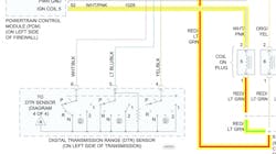
In a two-wire COP system, the switching of the coil ground is almost always done by the engine control module (ECM) or powertrain control module (PCM). In this diagram of a two-wire COP unit on a 2004 Ford Truck F 250 4WD Super Duty V10-6.8L, the RED/LT GREEN is “hot” with Key On. The WHT/PNK is the switched ground (square wave) from the driver transistors in the ECM/PCM.
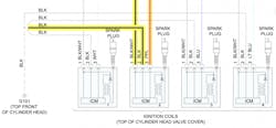
In this three-wire variation on a COP system found on the 2016 Honda Accord Sedan L4-2.4L, the BLK wire to terminal 1 on each of the four COP units is a full-time ground. The BLK/WHT wire on terminal 2 of each COP is switched B+ from the ignition relay. The remaining wire to terminal 3 (PPL for COP #2) is the switched ground trigger from the PCM for the COP.
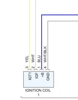
In this four-wire system example from a 2015 Toyota Camry L4-2.5L, we have GND, our B+, the switched ground trigger IGT1, and a fourth wire labeled IGF or ignition feedback. The IGF is an ignition confirmation signal which sends a signal to the PCM/ECM every time the coil fires properly. After a dozen or so ignition cycles with no confirmation signal, the PCM/ECM will turn the fuel injector off for that cylinder to protect the catalytic converter from damage. Because of this design, if the problem vehicle has an opening in the IGF wire or a COP that is not outputting a signal on the IGF terminal, you will have a misfire on that cylinder.
Now that we have an understanding of how coils can output over 40KV (shocking, isn’t it) and we’ve seen how COP timing is accomplished, let’s look at some simple diagnostic procedures.
A simple and quick misfire diagnosis procedure
Try the “coil swap test” to determine if a defective coil is the cause of a misfire. Do not perform on a system with an IGF circuit. This test only works where you have access to all cylinder COP units.
If your spider-sense tells you there’s one cylinder that isn’t contributing its fair share, this is a simple way to first verify which cylinder is not producing power and then confirm or deny that the COP unit is the culprit.
- With the engine at idle start at an easily accessible COP unit and unplug it. If that cylinder is operating, disconnecting the COP should result in the idle becoming rougher. If that cylinder is OK, move on to another COP and unplug it. Eventually you will unplug a coil and there will be very little or no change in engine operation. You have now found the “slacker” cylinder. Shut the engine off and mark it “??”
- Remove that question-marked coil. Remove a previously tested COP unit from a good cylinder and mark it “Good” with a felt pen or paint marker. Do not use a pencil – graphite in the pencil is conductive.
- Swap their locations so that the “Good” COP unit is now installed at the cylinder that was inoperative earlier.
- Start the engine and let it idle. Unplug the COP that is marked “Good.” If there is a substantial increase in roughness, the COP formerly known as “??” is defective. Replace it. If this is a high mileage vehicle, consider replacing all the coil-on-plug units. You may find that it is not significantly more expensive to buy a set of COP units as opposed to one or two.
- If the problem remains at the cylinder with the “Good” COP unit, you have to move onto determining if the problem is still ignition related, or perhaps fuel related (injectors or injector control circuit), or a mechanical issue like lifters, valves, or a vacuum leak.
Another way to test COP operation – and this one works for no-start problems
The previous test is great for testing misfires but not so good for no-start diagnosis on a COP-equipped vehicle. But there is a special tool that can help. This little gem, ladies and gentlemen, is a COP quick probe. While an assistant cranks the engine, you simply place the paddle end against the top of the COP unit and look for a flashing light on the quick probe. And of course, the quick probe can also be used for misfire diagnosis in much the same manner. If the light flashes on all but one COP, that COP unit is not functioning. Perhaps this is due to a lack of a trigger from the ECM/PCM, but it can also be due to a defective COP unit or a break in the wiring.
A “flashing light” means:
- The computer is commanding that COP unit to work
- The ECM/PCM is getting the signals it needs from the crank position sensor (CKP) to know when to trigger the COP
A “flashing light” does not mean that you’re done with the diagnosis.
If you have observed no flashing at the tool while cranking, seek out the wiring diagram for the COP circuit and check for B+ power on the COP units with the key in the on position. If you have power at the COP units, grab the scan tool, crank the engine, and look for an RPM signal on the PIDs. No RPM may indicate a failed CKP or worse. A fellow tech once spent 30 minutes trying to determine why there was no spark. He then determined that there was no RPM signal. A CKP sensor was installed but to no avail. On this car, the CKP read off the crankshaft pulley. The pulley was no longer spinning with the crankshaft due to a sheared keyway caused by a loose crank pulley bolt.
Wait, there’s more…
At this point, the more seasoned among you are wondering when we’re going to mention using a lab scope or “DSO” (digital storage oscilloscope). It’s a great tool and can save the day when used properly. However, using a DSO is beyond the scope of this article.
Try the simple tips we’ve shared here and you’ll improve your skills in diagnosing COP failures. Keep learning and keep earning.
Information provided by ALLDATA


