This article was originally published Nov. 1, 2010. Some of the information may no longer be relevant, so please use it at your discretion.
The headline might give you the impression that the subject is all about testing coils, spark plugs and plug wires, but I am referring to analyzing the electron behavior in the combustion chamber. The objective is to look at the effect of fuel mixture, valve seating, compression, carbon deposits, and other symptoms that affect this behavior. The ultimate goal is to learn the logic of scope pattern interpretation.
Why a scope if you have a scan tool?
Very few shops have a scan tool for every vehicle, and using a scope for driveability problems is an alternative. The scan tool might spot a misfire, but the scope does more than just find the location. It identifies under what conditions (speed or load) the problem occurs and provides a chance to evaluate the cause. Because you can compare each cylinder under the same load or driving condition, you can show the customer potential future misfires and prevent comebacks.
Let us make the assumption that you have a lab scope, but you don't have, or are not using, the ignition leads. If we can illustrate that total ignition analysis can be accomplished within fives minutes after hookup, would you reconsider and investigate the wonderful world of exploring electron behavior inside the combustion chamber, and the ability to observe fuel distribution per cylinder?
The secondary ignition waveform
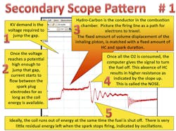
As seen in Figure 1, the voltage required to fire the plug is determined by the greatest gap in the circuit. It is not a measure of all the gaps in the system. A better terminology would be "dominating gap," because kilovolt (Kv) demand increases with spark gap under compression. If a 0.045" gap outside the combustion chamber requires 2 Kv to jump the gap, this same gap under compression may require 10 Kv for the plug to ionize, providing fuel is present to help conductivity.
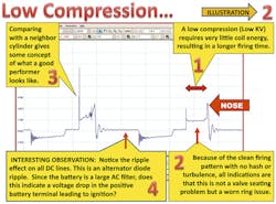
A good example is Figure 2, where a cylinder lost compression, and we see less kilovolt demand increasing the firing time. The opposite is true when the kilovolt is high. We learn that kilovolt is a necessary parasite, robbing from the burn time in the combustion chamber.
Kilovolt does not burn fuel, firing time does. A lean fuel mixture, (reduced HC) causes the kilovolt demand to increase even more in proportion. Therefore, an insulation breakdown causing a misfire is most often the result of unusual high kilovolt demand created by any combination of worn spark plugs and lean mixture.
Replacing a part to see if the misfire goes away without knowing the cause is a fruitless exercise. Crossfire occurs when kilovolt is driven high beyond the capacity of the insulation. Then the spark is enticed to find a path to ground outside the combustion chamber. When that happens, there is no HC present outside the combustion chamber to sustain conductivity resulting in high resistance creating shorter firing time at a higher kilovolt level.
For practical purposes, there is no current flow until the plug fires as indicated by the firing time. When the coil output runs out of energy, the residual energy dissipates into oscillations. Because hydrocarbons (fuel) are conductors, they not only assist in the ionization process but also affect the conductivity during firing time.
How do we know it is a plug wire?
Let us assume a cylinder at idle showed abnormally high kilovolt, and the firing time seemed to be shorter compared to the other cylinders. We need to find out where that high kilovolt is created, internally or externally. Play with the throttle, accelerate and decelerate and watch the response. If the kilovolt stays high, this indicates that the greatest gap was external. How should the scope respond to rpm increase?
At 2,000 rpm, the timing advance is between 30 and 40 degrees BTDC. At that time, the piston barely starts the compression stroke resulting in less compression when the plug fires. Therefore the reduced kilovolt tells us that the timing advance is functional, and there was compression. We have verified the greatest gap is indeed in the combustion chamber and not external.
What about fouled plugs?
Scope analysis has a lot to do with common sense. Let us imagine what a fouled plug looks like on the scope. No picture to memorize, just use your imagination. There is no spark gap, and therefore, no nose or residual energy left. Because carbon resistance replaces the spark gap, the coil energy is drained off, as indicated by a curved slope from the kilovolt spike to the dwell line.
Resistance of carbon foul could be as high as 2 Megaohms demanding more kilovolts than, for instance, a wet plug caused by a dripping injector. How do we know the difference? Very simple!
Leaky Injector:
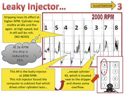
At low rpm, it might look like a fouled plug, but at higher rpm, the dripper might start firing because there are fewer drips between firing events, but when this cylinder fires, the fuel mixture is still rich, and the scope shows a lower kilovolt plus a longer firing time with hardly any nose. The computer looks at that dripper as too rich and subtracts fuel, driving the other cylinders extremely lean (Figure 3).
There is one exception: the cylinder next in firing order, which benefits from the overflow of the dripper. With computer controlled engines, total engine analysis of all cylinders tells us the complete story and verifies diagnosis, and that is important to save valuable time.
Exploring firing time
The coil output is designed to maintain the firing event for as long as there is controlled fuel in the combustion chamber. Because a collapsing magnetic field determines coil energy, engine rpm, or load doesn't affect it. The firing time indicates how well this energy is used in burning the fuel mixture. After establishing the validity of the electrical components at idle, firing time is our ruler to measure conductance.
Because all cylinders and injectors on that engine are created equal, comparing the firing pattern is the easiest method to seek out the cylinder that is different.
Lean injector:
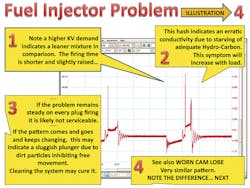
In Figure 4, we noticed that cylinder B has a shorter firing time. The absence of hydrocarbon is particularly visible at the end of the firing time, where it terminates with a high nose. It is as if the coil is saying, "It's not my fault, there is plenty of energy left."
However, there is something else to observe in cylinder B. The evidence of a lean condition already starts at the beginning of the firing time with a higher kilovolt demand and higher firing line starting point in comparison.
Comparing with a good performing cylinder at the same speed or load is essential. How do we know that "A" is OK?
- Note there is no coil energy wasted in high kilovolt demand.
- Consider the smooth conductivity of the firing line of total combustion as long as there is coil energy available.
- The nose tells us to what extent coil energy is used up to burn all the fuel. This is a perfect match of air, fuel and spark duration.
We do want to know the where, when and how before drawing a conclusion. Besides location, it helps to know how many cylinders are affected, and what the rpm or load was when the problem occurred. It does not take any skills of scope pattern interpretation to identify a shorter than normal or greater than average firing time to pinpoint the oddball.
Any short spark duration indicates a higher resistance either due to high kilovolt or reduced HC. A longer firing time indicates a lower than average resistance.
Helpful hints in scope pattern interpretation
Anyone who knows Ohms Law understands that the effect of resistance is in direct proportion to current flow. When we have a poor connection at the battery post of as little as 0.01 ohm with the headlights turned on, it creates only 0.1V drop — not even noticeable in brightness.
However, during cranking, that same resistance at 300A cranking load means 3V less at the starter. This certainly will slow down the cranking speed. This also holds true for air flow or fuel flow. A kink in a garden hose does not make much difference if you want a cup of water, but it becomes a problem when sprinkling the lawn. A fuel filter restricted at 80 percent will not make any difference at idle, but the car will not have the horsepower to make it uphill.
The point is simply that testing under load makes all the difference to complete performance analysis. Because you have the scope hooked up, it might take less than a minute in the bay or up to 20 minutes on a test drive. There are different options or methods of testing under load, but they all have two things in common:
- It needs to be done with someone in the driver seat.
- The leads need to be long enough to reach the equipment inside the vehicle.
Test Results Under Load
Resistance and restriction or obstruction all mean the same thing and will have the greatest negative effect when the demand for flow is high. Let us explore examples.
Restricted exhaust
When the engine cannot exhale properly, all functions are affected. The firing line on the scope showing perfect at idle, becomes ragged and shows turbulence progressively getting worse under load disturbing all cylinders. Plus, EGR is doubled or tripled.
Under normal conditions, the EGR valve re-circulates about seven percent of the exhaust gasses into the intake. However, with even a small exhaust restriction this might increase to 30 percent or more. Momentarily inhibiting the EGR valve from functioning, while watching for improvement on the scope pattern, is one way to verify restriction. Restriction will cause reduced volume and is not a lean mixture as it is sometimes called. It is not affecting the air/fuel ratio.
Dual exhaust
This, from separate banks, can play tricks if one bank is restricted. The good (non-restricted) bank will look extremely lean on the scope pattern with a high nose, while the restricted bank seems to have a richer fuel mixture with hardly any nose. Let us assume that bank No. 1 is 50 percent restricted.
The MAF sensor will report this reduced flow as 100+50 divided by 2 is 75 percent of total flow to the combined banks. The computer distributes an equal amount of fuel to both intake manifolds.
The good bank No. 2 inhales 100 percent air and gets 25 percent less fuel allotment. The restricted bank No. 1 inhales 50 percent air and gets the same amount of fuel. That is 25 percent more fuel than this bank requires. See if you can find a lean cylinder and a rich cylinder in the figures that will match bank 1 and bank 2.
Worn Cam Lobe
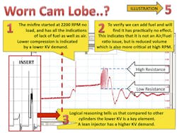
This problem is not a daily occurrence, but we're exploring how to interpret what the scope is trying to tell us in the waveforms. Figure 5 looks almost similar to the lean injector in Figure 4 or 7, but the difference is in the kilovolt demand, and the level where the firing line starts. We need to compare this with a good cylinder (see Figure 5). This is a case of reduced volume of HC and not a lean air/fuel ratio.
When there is less volume of both air and fuel, there is going to be less compression, and therefore, a lower kilovolt demand. Misfire depends on how severe the valve lift is affected. With a 20 percent lower cam, the misfire might occur beyond 2,000 rpm, while a 40 percent reduction in valve lift might begin misfiring at 1,600 rpm. No lift at all obviously will be dead at any rpm.
Inadequate fuel supply
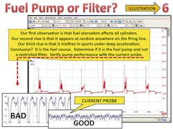
Whether the reduced fuel source is caused by the fuel pump, pinched fuel line or dirty fuel filter, the scope does not know the difference. When you take a close look at Figure 6, you will notice the fuel starvation could be anywhere on the firing line. The next step is a simple current test as illustrated. Under load, the engine might start to buck and hesitate, but long before the intermittent misfire happens, indicators are present as flashes, moving arbitrarily from cylinder to cylinder progressively getting worse with increased load. This is where preventive maintenance pays off.
Misfire under load
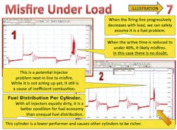
When a misfire code tells you which cylinder is at fault, it is like diagnosing blindfolded because you still don't know why the condition, when, or how often it did repeat, and how many other cylinders are close to the same ordeal. Figure 7 indicates the misfire was fuel related with only about 25 percent active combustion. We also know that it is not an intake leak because it appeared only under load.
We can tell that it was not lean at the start, because kilovolt demand is normal and the firing line is not elevated. We can readily see it is not a dirty screen or an odd spray pattern. If this pattern remains permanent and does not vary, it is not cleanable and is likely a high electrical resistance problem getting a late start. A simple replacement of the injector would suffice. The fact that a scope can provide all that information in detail eliminates trial and error repair methods.
Valve seating
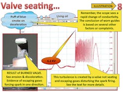
This is a common but often neglected problem. When a valve is not seated, it does not cool, which might lead to a variety of possible failures. It is easily spotted with a scope at idle, preferably in drive. A non-seating valve, whatever the cause, allows compressed gases to escape. Everyone knows that a burned valve is very noticeable at idle, but at 60 mph, that small crack does not make much difference because there is not enough time to escape. For that reason, testing at low speed is essential.
The other reason for analyzing at idle in drive is because the spark occurs near TDC when compressed gas movement is at its peak. The effect of these escaping gasses can be seen on the scope as a hash at the beginning of the firing line (Figure 8).
We will see a low kilovolt because of low compression, directly followed by hash caused by air flow distorting the spark. Depending on frequency, the problem could be traced to worn valve guides, carbon deposits, weak valve spring or poor lubrication. Conclusive diagnosis depends on how many cylinders are affected and if the problem is intermittent or permanent.
The value of a scope is apparent only when the potential is fully understood. Let us assume that every cylinder performed as it was designed. The air inhaled is determined by bore and stroke of the piston. This air is matched with a precise amount of fuel and the process of total combustion matches the coil output energy with very little residual energy to spare. All cylinders are created equal and should follow that precise pattern of combustion efficiency. Any deviation will affect the firing time and alter the residual coil energy. Because the lab scope is time based, there is no better tool to measure, compare and display combustion efficiency per cylinder.
Mac Vandenbrink is owner of Dynamic Auto Test Engineering Corporation (DATEC), a company focused on designing new training concepts and teaching them to the automotive aftermarket.
