In a recent article about the 6T70 series transmission, the subject of performance codes replacing gear ratio error codes was mentioned. The article covered in part a little about diagnosing these types of codes. Originally, we saw performance codes being assigned to shift solenoids. And if I have my facts correct, I think it was Ford that first began assigning performance codes with pressure control solenoids.
As time has progressed, we are seeing more transmissions having solenoids handling both the shift scheduling and shift feel simultaneously. Performance codes for these types of solenoids have a different approach than say, a shift solenoid being used to just control shift scheduling.
In our 2014 ATSG seminar that we do in various cities across the country, we used two different Toyota transmissions as an example of one approach a tech can make when dealing with a shift solenoid performance code. The idea with this specific diagnostic approach is to determine as quickly as possible if there is a major or minor repair associated with the performance code. The information we provided in this seminar is as follows.
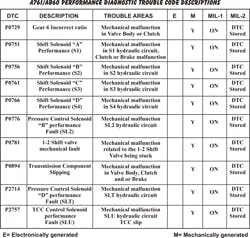
A Toyota Tundra, 4Runner, Tacoma, Sequoia and FJ Cruiser and Lexus equipped with the A750, A761 or AB60 transmission might exhibit intermittent performance diagnostic trouble codes (DTCs). These DTCs have very vague descriptions and can cause confusion during diagnoses, which typically incurs additional expense because of replacing parts that are good.
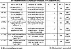
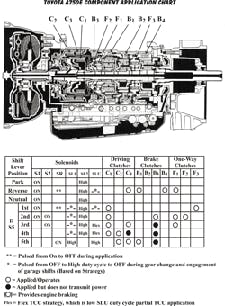
The next step is the most important. A thorough road test must be performed comparing the performance of the vehicle with scan tool data along with all the information provided in Figures 1 and 2. The conclusion will provide a direction as to whether this trouble code is a minor or major repair.
Using code P0751 in the five-speed A750 transmission as our first example, Figure 1 informs us that this is a malfunction with the hydraulic circuit for Shift Solenoid A (SSA) or (S1).
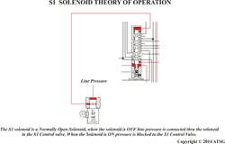
Looking at the component application chart in Figure 2, which includes the solenoid firing order, SSA is on in the Drive positions 1st and 2nd gears. It is off in 3rd through 5th gears. Also note that in the same application chart that when the SSA (S1) solenoid is turned off the C3 Clutch is applied. In other words, there is a direct correlation between SSA (S1) and the operation of the C3 Clutch.
When road testing the vehicle, keep in mind the function of the solenoid and the application of the C3 Clutch. After the road test the following questions would need to be answered:
A. Did it take off in 1st gear, or did it feel like it was taking off in 3rd while the scan tool
shows that SSA (S1) is commanded On?
B. If it took off in 1st, did it shift into 3rd gear?
C. If it shifted into 3rd, did it slip during the transition?
D. If it slipped into 3rd does it delay in Reverse?
The target areas for questions C and D would be related to the operation and integrity of the C3 Clutch assembly. Note: This same trouble code can set from a C3 Clutch that is not holding or is slipping. Refer to Figure 1 and note that the C3 Clutch is On in Reverse as well as 3rd. This would mean that if the C3 clutch was slipping, problems should be observed in both 3rd and Reverse.
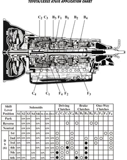
Refer to Figure 5 for a component application chart including solenoid strategy. Study the chart and note that SSA or S1 solenoid is off in the Drive position First gear and on in 2nd thru 6th gears. Also note that in the same application chart that when the SSA (S1) solenoid is turned On the B3 Brake is applied. Now, road test the vehicle while keeping in mind the function of the solenoid and the application of the B3 Brake.
After the road test the following questions would need to be answered:
B. If it took off in 1st did it shift into 2nd gear?
C. If it shifted into 2nd gear, did it slip during the transition?
D. If it tried to shift into 2nd gear, did it have a quick cut loose until you let off the throttle and it shifted into 3rd and then shifted thru the rest of the gears fine?
The target areas for questions C and D would be related to the operation and integrity of the B3 Brake assembly. Note: This same trouble code can set from a B3 Brake that is not holding or is slipping. Refer to Figure 5 and note that the B3 Brake is On in Second as well as the F2 freewheel. Problems in the F2 may be better described in question D.
Once the diagnosis has been performed the solution is simple based on answering the questions listed in each section. As you can see it is very important to not only have the correct definition of the code but to connect the trouble code to a problem area in the test drive. Once the test drive is completed a target area is unveiled and finally the solution can be performed.
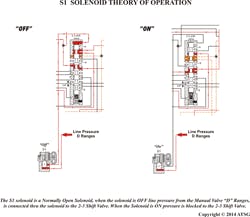
Also note that it is very important to have oil circuit diagrams so not only the hydraulic function of the solenoid can be observed but the valve and or valves that are connected to the solenoid can be checked. Refer to the ATSG website under our bookstore for hard to get oil circuit diagrams under the heading “Technician Guides.” Check in periodically as the library of hydraulics continues to grow as new Tech Guides are developed. The ZF8HP, the A6MF1 and the new 2nd generation 09G will be added to the list soon.
About the Author
Wayne Colonna
POWERTRAIN PRO Publisher
Wayne Colonna is president of the Automatic Transmission Service Group (ATSG) in Cutler Bay, Fla., and a frequent speaker/instructor for transmission training around the globe.
