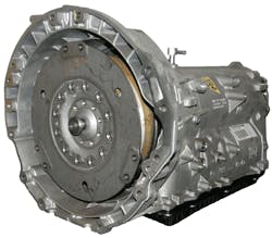
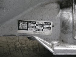
The Aisin AW Co., LTD has consistently been the first to market with several different types of automatic transmissions. The longitudinally mounted 8 speed automatic transmission called the TL-80SN (figure 1) is one of these transmissions. It is being used in a variety of Lexus vehicles as far back as 2007 and is now in the 2014 Cadillac CTS. Lexus refers to this transmission as the AA80E transmission.
But the TL-80SN is a sleeper in that you do not hear much about the transmission but then you suddenly have one come into your shop and you do not know much about it. This article is designed to get you familiar with this unit so this doesn’t happen to you.
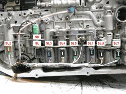
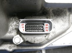
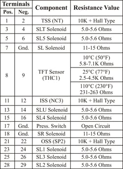
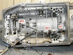
Another plus is the computer is mounted externally so the external wires going to the transmission (figure 5) allows for checking speed sensor signals and solenoid commands. A chart in figure 6 can be used for bench testing the internal electrical components. Solenoid resistance values are checked at 20°C (68°F).
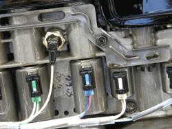
The Transmission Pressure Switch (TPS1- figure 8) is a normally open pressure switch. It monitors SL1 pressure. If checking this switch while in operation (connector plugged in and you are back probing wire 17), there will be less than 1 volt on this wire in 1st through 5th gears and will read near 12 volts in 6th, 7th and 8th.
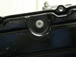
The fluid fill procedure needs to be performed within a specific temperature range and is accomplished in the following manner.
Procedure for an entire transmission fill:
2. Remove the refill plug and overflow plug.
3. Fill the transmission through the refill hole until fluid begins to trickle out from the
overflow tube.
4. Reinstall the overflow plug.
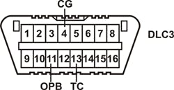
5. Adjust level by using SST 09843-18040 to connect terminals 4 and 13 for non-
air-suspension vehicles and 4, 11and 13 for vehicles with air-suspension in the DLC3
connector shown in figure 10.
7. AC Must be turned off
8. Slowly move the shift lever from P to S, then move the shift lever from the 1 to 8.
Then return the shift lever to P.
9. Move the shift lever to the D position, and quickly move back and forth between N
10. This will activate the fluid temperature detection mode.
11. Indicator light (D) remains illuminated for 2 seconds and then goes off.
12. Return the shift lever to the P position and disconnect terminals 13 (TC) and 4 (CG) –
non-air susp. application
applications
14. Idle the engine to raise the temperature of the ATF.
15. When the indicator light (D) turns on, lift the vehicle up immediately (off = temp too
low, blinking temp too high).
17. Remove the overflow plug at the proper fluid inspection temperature, check the fluid
amount.
Fluid capacities are as follows:
Transmission valve body removal......................... 4.2 liters (4.44 US qts. 3.70 Imp. qts.)
Torque Converter removal..................................... 6.7 liters (7.08 US qts. 5.90 Imp. qts.)
Entire Transmission assembly................................ 9.9 liters (10.46 US qts. 8.71 Imp. qts.)
This transmission requires Toyota Genuine ATF WS transmission fluid.
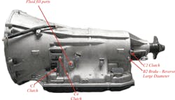
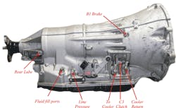
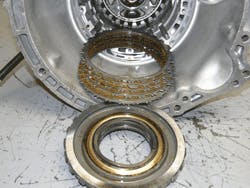
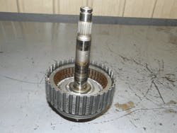
The placement of the clutch assemblies begins with the B1 brake located right behind the pump (figure 13). Next to come out are three driving clutch assemblies. From left to right; the C1, C3 and C4 (figure 14). Then next two components is a one-way-clutch (F1) and the B2 brake clutch assembly (figure 15). The last clutch assembly all the way in the rear of the transmission is the C2 driving clutch (figure 16).
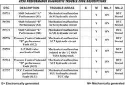
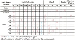
When you compare solenoid activity with clutch apply, you’ll see how each of the solenoids have control over their respective clutch assembly. If you read a previous article in Powertrain Pro about GM’s 6T40 series transmissions, I made a comment about gear ratio codes being replaced with solenoid performance codes. This transmission utilizes the same strategy. You will not see P0731, 732 etc. for gear ratio errors. You will pull solenoid performance codes in their place.
One helpful last point related to solenoid codes is the way these solenoids may be identified. The SL solenoid will be referred to as the TCC Solenoid while the SLU will be referred to as the TCC Pressure Control Solenoid. SL1 may be called Solenoid A, SL2 as B, SL3 as C, SL4 as G, SL5 as H, SLT as D and the SR as E.
About the Author
Wayne Colonna
POWERTRAIN PRO Publisher
Wayne Colonna is president of the Automatic Transmission Service Group (ATSG) in Cutler Bay, Fla., and a frequent speaker/instructor for transmission training around the globe.
