The ins and outs of Ford's Electronic Automatic Temperature Control
Content brought to you by Motor Age. To subscribe, click here.
What You Will Learn:
• Computers monitor and control the modern HVAC system, maintaining better temperature control of the cabin
• Diagnostic direction can be gained from viewing HVAC scan tool data
• It's important to get to the root-cause of the fault to avoid comebacks
There was a time when automotive air conditioning was an option, and dashboard heat had two settings: “not very hot” and “melt your floor mats.” Maintaining a comfortable cabin climate required a choreography of heat on, heat off, and opening the windows (just a crack"). Today's set it-and-forget-it world mandates a one-touch solution to cabin creature comfort.
Ford's Electronic Automatic Temperature Control (EATC) uses sensors, modules (computers), and electric motors to maintain a desired temperature inside the passenger compartment. The system controls airflow, air temperature, and air volume to sustain the comfort level selected by the vehicle's occupants. Dual Automatic Temperature Control (DATC) allows the driver and the passenger to enjoy their own individual temperature zones.
This article will discuss the inputs, the outputs, the components, and the strategies that drive the Ford EATC. We'll spend very little time discussing base climate control. I'm sure you understand how an A/C compressor and a heater core operate.
It begins with airflow
The plenum is the base of operations for EATC. The plenum houses a maze of doors designed to direct pressurized air through a series of passageways and corridors. Air temperature, air distribution, and air speed are determined inside the plenum, located behind the dash panel.
EATC mode of operation can vary significantly due to the model and model year. So instead of trying to cover every quirk of every model, let's concentrate on the areas that can be the most beneficial in helping you diagnose and repair an EATC concern. We'll start with airflow and distribution.
The job of the blower motor is simple. It pulls air in then pushes the air throughout the plenum. Blower speed is regulated by the blower speed controller when in auto mode, and the controller is commanded by the HVAC module. Not all models are equipped with an HVAC module. On some models the front control interface module (FCIM) oversees EATC functions.
The blower motor speed controller governs the blower motor's ground side resistance, much like a manual resistor. The controller receives a pulse-width-modulated (PWM) signal from the control module and provides a variable ground circuit to the blower motor. The positive side of the blower motor receives power from the blower motor relay. On some models, this current is diverted through the blower speed controller on its way to the blower motor.
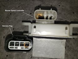
When diagnosing an inoperative blower motor in a Ford EATC system, start with the basics. With the circuit intact hook up your test light across both pins at the blower motor connector and turn it on. If the light illuminates (indicating available voltage and ground), and the blower motor doesn't turn on, you have a faulty blower motor. If the test light doesn't illuminate, jiggle the harness connector at the blower speed controller. Remove the connector and examine it for signs of terminal tension issues. There have been many issues with the connectors and the pins getting a bit crispy due to heat generated by the controller (Figure 1). If you don’t find a problem there, you’ll need to determine if the blower motor is missing either voltage or ground supply. You’ll need to test both sides individually with your test light.
By now, you should have the wiring schematic opened. If voltage is missing check the fuses. If the fuses are good, swap the blower motor relay (You can remove a different relay from the battery junction box [BJB] and use it to replace the blower motor relay temporarily). Be careful when choosing the surrogate relay. Not every relay is the same. Be sure that the part numbers on both relays match. If the blower is still inoperative, it's time to hook up the scanner.If you were not lucky enough to locate the problem during the basic electrical pre-diagnosis, you should hook up the scanner and follow the pinpoint test. Always proceed with the test that is specific to any DTC that may have been generated. If there is no DTC, perform the diagnosis by symptom pinpoint test.
Numerous steps in the pinpoint tests require you to install a fused jumper wire between designated circuits and record the results. Don't get lazy and use a non-fused jumper wire. Keep in mind that you're testing a system with an unknown fault. Any wire could be shorted to ground or shorted to voltage. Even a defective blower speed controller can become a straight path to ground. It only takes a minute to fuse a jumper wire.
Next, it’s about air distribution
The forced air that leaves the blower motor is directed to the defroster vents, panel vents, and floor vents utilizing a series of doors. Earlier EATC systems used as many as three doors to direct air through the plenum. Each airflow door was independently actuated by a vacuum motor or an electric actuator. Over the years, this configuration has been streamlined to one door and one actuator.
An electric actuator containing an electric motor operates the defrost/panel/floor mode door. A potentiometer located inside the actuator reports the mode door position back to the ECM.
When EATC is in the "auto” position, the ECM determines air distribution mode based on temperature requirements. If it fails, the air distribution actuator will usually generate DTC B1086. DTC B1086:07 indicates a mechanical failure. A stored B1086:07(without accompanying circuit codes) means that either the mode door is binding, the actuator isn't moving, or the potentiometer isn't reporting the position's change to the ECM.
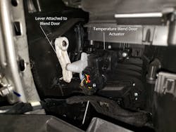
It's imperative to check for a binding mode door or linkage before condemning the actuator. The only sure way to do this is to remove the actuator and work the mode door by hand. The door should move smoothly and effortlessly throughout its entire range of motion. If the door moves freely, and you have no circuit codes, replace the actuator (Figure 2).
An electric actuator also manages the inlet air door. Whether fresh air or recirculation mode is selected, the actuator moves the inlet door to the desired position. The inlet door will always remain in recirculation mode when the AC is in the "max” position.
The most common concern with EATC is insufficient air discharge temperature. Before digging into EATC diagnosis, be sure to check climate control basics. EATC is an operating strategy and can only work as well as the system it operates.
Monitor inputs to troubleshoot the outputs
Several inputs need to be within range for the ECM to engage the A/C clutch coil. One such input is the evaporator temperature sensor. The evaporator temperature sensor is used in place of a low-pressure cycling switch to regulate the A/C clutch's on/off times. The ECM turns the clutch off when evaporator temperature drops below 32 degrees F and turns it on at 35.6 degrees F. Since the purpose of cycling the clutch is to prevent evaporator freeze-up, shutting it down at 32 degrees F. is a lot more efficient than using low side pressure to determine clutch cycling downtime.
When an evaporator temperature sensor malfunctions, the ECM usually defaults to -40 degrees F., which prevents A/C clutch activation. This is a common scenario, and after checking the basics, it should be the first thing you look at when diagnosing an inoperative A/C clutch coil. View the EVAP_TEMP PID on your scan tool. If the value is above 35.6 degrees F., the evaporator temperature sensor isn't the cause of the problem. A defective evaporator temperature sensor might generate circuit DTC B1B71, but don't count on it.
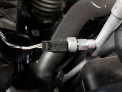
The A/C pressure transducer (ACP) is another input that will inhibit A/C clutch engagement. Located on the discharge line between the compressor and the condenser, the ACP reports A/C discharge pressure to the ECM. The ECM will not engage the A/C clutch If the transducer reports that A/C pressure is too high or too low. To check ACP operation, hook up your manifold gauges while viewing the ACP_PRESS PID on a scan tool. The PID should show within ± 15 psi of actual pressure (Figure 3).
A customer recently brought in his 2015 Explorer complaining that the air conditioner would intermittently stop blowing cold air. I wasn't able to reproduce the issue. I found that the ACP was showing 71 psi over actual discharge pressure. Based on the ACP's erroneous value, the ECM was shutting the compressor down 71 psi too soon. Replacing the ACP fixed the concern.
The ECM will also shut down the A/C compressor if engine temperature is too high, or if ambient temperature is too low. So, monitor engine coolant temperature (ECT), cylinder head temperature (CHT), and ambient air temperature (AAT) when diagnosing an inoperative A/C clutch.
Hooking up a scan tool to a vehicle after an overnight cold soak is a good way to check the temperature sensors. The AAT, CHT, ECT, and the intake air temperature sensor (IAT) should all be reading about the same temperature after an overnight rest. The powertrain control module (PCM) runs this exact test after a cold soak of about six to eight hours and will inhibit A/C clutch engagement if just one sensor differs greater than a calibrated value.
It’s always about temperature
Faulty temperature blend door operation is a common cause of unsuitable climate control discharge temperatures. A temperature blend door actuator is an electric motor, not unlike the ones we've previously discussed. They manipulate the temperature blend door to direct airflow through the heater core and the evaporator as needed to maintain the desired cabin temperature. Dual automatic temperature control (DATC) utilizes two blend door actuators, one for each side.
Monitor blend door PIDs using a diagnostic scan tool. When diagnosing DATC, monitor the LEFT_BLEND and the RIGHT_BLEND PIDs and operate the actuators using the scan tool. If the PIDs show an increase and a decrease in percentage value, and the air temperature changes correspond, the blend doors are working (Figure 4).
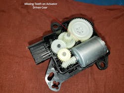
Sometimes when an actuator experiences a mechanical failure, it will make a banging noise during attempted operation. This is the case with temperature blend door actuators, recirculation door actuators, and air distribution door actuators. The banging sound results from either the nylon drive gear or the nylon driven gear inside the actuator missing a few teeth. The actuator gets stuck on that spot, and since the potentiometer is reporting no change of position to the ECU, it keeps trying to change the actuator position.
To locate the jammed actuator, operate the controls. The change you initiate that causes the actuator to start banging determines which actuator is bad. If you can access it with your hand, you can feel the actuator banging. Be sure to check the door for binding after removing the actuator (Figure 5).
Actuators mesh with their respective doors utilizing a lever or a splined shaft. The splined shaft is keyed to assure that the actuator is installed in the correct position. Here's a helpful hint. Cut the shaft off of an old actuator and use it to manually operate the blend door when checking for binding or sticking.
The get-up-and-go of EATC
Here's an overview of the operation of DATC on a 2014 Ford Fusion with the selector set to auto and the desired temperature set to 64 degrees F. for the left side and 75 degrees F for the right side. The ambient temperature is 90 degrees F.
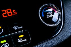
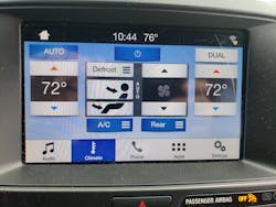
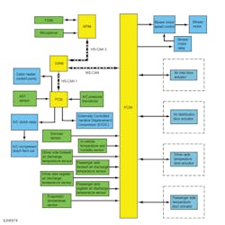
The driver selects “auto” and sets the temperature using either the buttons on the front control interface module (FCIM) or the touchscreen on the front display interface module (FDIM). An 8″ touchscreen is an option on vehicles equipped with the Ford Sync System (Sync) (Figure 6). The driver can also use Sync voice commands to make climate control requests. Orders initiated using Sync are received by the accessory protocol interface module (APIM) and sent to the gateway module (GWM).
The GWM relays this information to the PCM and the FCIM. The FCIM monitors the in-vehicle temperature and humidity sensor to determine if air conditioning or heat is needed to achieve the desired cabin temperature. If all the critical conditions are met, the PCM energizes the A/C clutch coil. The PCM monitors ACP and interrupts the A/C clutch operation if A/C discharge pressures go too high.
The FCIM monitors and adjusts the air inlet door based on cabin humidity and temperature. The module switches to outside air if the cabin becomes too humid, and if more cooling is needed, it will open the door to recirculation. Air is distributed to the panel vents for air conditioning and the floor vents for heat. The driver selects “defrost”. The FCIM also coordinates the temperature blend door actuators to meet the driver's and the passenger's temperature requirements.
In the case of this 2014 Fusion, the FCIM will direct colder air to the driver's side for an extended amount of time to compensate for the difference in desired temperatures.
The blower motor relay is energized by the FCIM, which sends power to the blower speed controller. The controller changes blower motor speed by alternating the blower motor ground side resistance. Blower speed will always go to high if MAX AIR or defroster is selected. Blower speed will decrease as cabin temperature gets closer to desired. The operator can change the blower motor speed at any time.
The superhighway of network communication
All this chatter between modules means that climate control diagnosis can quickly morph into network diagnosis. If a network issue is causing an EATC concern, you should retrieve at least one "U" code from at least one module.
A network communication issue does not always mean that there's a fault. Sometimes a module can lock up due to excessive traffic (messaging) on the controller area network. The FCIM seems to be prone to this sort of thing. Before diving into network diagnosis, perform a battery disconnect. Disconnect the negative battery cable, then touch the negative terminal to the positive post. This will discharge the modules and allow them to reset. Wait a couple of minutes, then reinstall the cable. Quite often, this fixes network communication issues. If the concern is still present, proceed with normal diagnosis (Figure 7).
A few more things
We haven't talked much about the in-vehicle temperature and humidity sensor. These sensors rarely go bad, but they can become inaccurate due to dust and dirt. A hose attached to the blower motor housing pulls a slight vacuum on the cabin sensor duct. This vacuum creates a small amount of airflow through the sensor, allowing for an accurate cabin air temperature reading. Unfortunately, it also pulls in little dust bunnies that restrict airflow past the thermistor. So, if the system is having trouble sustaining a consistent temperature, check the cabin sensor for contamination.
Recent model years are using panel vent temperature sensors. These sensors are located in the ductwork behind the vents. Vent sensors are a good diagnostic tool if an evaporator temperature sensor is suspect. Evaporator temperature and vent temperature should be very close to the same. Monitoring both is a good way to see if there's a problem.
Ford Motor Company's quest to assure their vehicles' occupants are comfortable goes way past what we've discussed in this article. There are climate-controlled seats, auxiliary climate control, and even heated steering wheels. Your most valuable tool to help you diagnose these features is your ability to understand how these things work. It's so important that I need to repeat it. Be sure to read Description and Operation before attempting diagnosis. Keep cool.
About the Author
Roy Dennis Ripple
Roy Dennis Ripple is a Ford Senior Master Technician and an ASE Master Technician with more than 30 years' experience in the automotive industry. As an automotive journalist, he is the recipient of a 2020 Azbees Award and a 2020 Tabbies Award. Ripple is currently working full-time as the shop foreman at a Ford dealership. He lives in New Jersey with his wife, three dogs, and two motorcycles. He can be reached at [email protected].
