When vehicles with electrical concerns come to your bay, do you run and hide or jump up and down with joy with anticipation of another electrical challenge? If not, why not? Electrical problem analysis can be very rewarding if the technician is properly trained and has the proper equipment.
After working with electrical problems for many years, I have found a few things that can help simplify electrical circuits and make your troubleshooting challenges a little less challenging.
• Electricity goes in circles and without a completed circle, it does not go. In other words, the electrical circuit must be complete for the circuit to perform its required task.
• Any simple circuit will have the same current flow anywhere in the circuit.
These few pieces of information seem very simple, but they are very important things to keep in mind when working on electrical circuits. I always smile when I hear someone say, “I have a short to ground, since there is voltage everywhere in the circuit. A short to ground would have one of two things, a blown fuse or a fire!”
When working on late model vehicles, there are several different kinds of circuits. There are computer communication circuits, computer sensor circuits, very high current circuits (starter supply circuits) and high current circuits such as headlight and taillight circuits. Each of these circuits conducts electricity but perform different tasks. This is a very good reason to familiarize yourself with the circuit before you start the problem analysis. Knowing what the circuit is designed to do and the purpose for its function will give you a head start on a direction before you start the testing process.
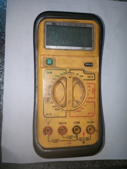
One great way to get an understanding of the circuit function is to study a wiring diagram. This might give you enough information to start the diagnostic process. You might need to dig a little deeper and research how the component or system works. Armed with this information, the technician will have a good idea which tool will be needed to analyze the problem and what settings on the meter to use. Time spent in research is time well spent and in the end will be a great value.
Each circuit in an automobile has one paramount purpose: to conduct current. Sometimes this current will be very low (in the micro amp range) and some circuits are designed to carry current in the hundreds of amps. This leads to a different diagnosticapproach on each kind of circuit. Testing a
Most electrical circuit problems can be narrowed down to four different kinds of problems: open circuits, short to ground, internal shorts between two wires in a harness or high resistance in the circuit. Each of these problems can be found easily, if you use the proper test equipment and proper test procedures. The object of diagnostics is to get the problem to come to you. Each type of electrical problem will require a different approach, although every electrical problem analysis should always start with learning how the circuit works, what the circuit does and how the circuit is laid out in the vehicle. Every piece of this information is found in the published service information for the vehicle.
Fun with Fuse 15
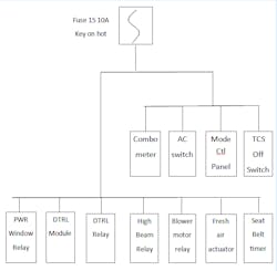
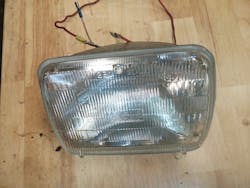
As an example of an intermittent short circuit problem, I will use a case study from a 1997 Subaru Legacy/Outback. This Subaru has been ridden hard and put away wet many times. The vehicle lives on top of a mountain and is driven two miles each way on washboard road every time it comes to town. The odometer is showing 208,000 miles and still has the original automatic transmission. The customer concern is that intermittently the instrument cluster lights will go out, the high beam headlights will go out, numerous instrument cluster lights will come on and if driven long enough, the engine will finally stall.
There are several diagnostic paths that can be taken on a problem like this. Some things I have seen used by techs to troubleshoot a shorted circuit include installing a higher amperage fuse to power the circuit or installing a circuit breaker in place of the fuse so the circuit breaker will still protect the circuit. This will close and supply power to the circuit and after all, this is an intermittent problem and we all know intermittent problems are hard, if not impossible to find. I do not like any of these diagnostic approaches so let’s think out of the box a little and use a solid diagnostic approach to the problem.
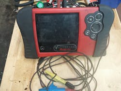
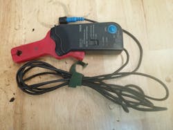
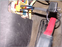
To accomplish this task, the system needs to be tested dynamically, which means to be able to make the short to ground happen in the shop where I can easily capture some data and pinpoint the location of the problem without having to take the car apart. The first thing is to install a fuse loop in place of fuse 15. This allows a low amp current probe and lab scope to record any current flow on the circuit.
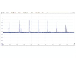
Since fuse 15 will blow when the car is being driven on rough roads, the way to get this problem to happen will be to cause some vibration to the dash. With all loads on the circuit turned off and the ignition key turned on, I started using my fist to bump the top of the dash. Within a few seconds, the labscope started recording amperage spikes as seen in Figure 8. At this point, I know the problem lies inside of the dash, but I’m not sure exactly where.
Back in the dark dungeon in the interior of the dash is one small steel brace for the radio. This wiring harness had been rubbing on that one little black steel brace for 200,000 miles and finally had rubbed a very small hole in the insulation. When examining the harness, the hole in the insulation was about the size of a straight pin head. There was just one little tiny copper speck showing through the insulation, which was on the back side of the harness and I had to use a mirror to see the problem.
About the Author
Albin Moore
Albin Moore spent the first 21 years of his working life in the logging industry. In 1992 he made the transition to shop ownership and opened Big Wrench Repair in Dryden Washington. Since opening the shop he has moved the business to specialize in driveability problem analysis, both with gasoline and diesel vehicles. Albin is an ASE CMAT L1 technician, and brings with him 40 years of analyzing and fixing mechanical and electrical problems. Albin enjoys sharing his many years to experience and training with the younger generation as a way of improving the quality of the automotive repair industry.

