Case Study: A/C inoperative unless 'magic' switch flipped on the dash
Content brought to you by Motor Age. To subscribe, click here.
What you’ll learn:
•How circuit continuity impacts component behavior
•How to use a DMM to diagnose open circuit failures
•How to use a DMM to perform fundamental voltage measurements
Vehicle information:
2003 Dodge Ram
195,000 miles
5.7L Hemi
Automatic Transmission
Complaint:
A/C inoperative unless the "magic" switch is flipped on the dash.
In my Introduction to Electricity and Electronics course, I was asked by a campus security employee to diagnose and repair an inoperative/compromised air conditioning system. The vehicle in question was a 2003 Hemi-equipped Dodge Ram (Figure 1). We were told that a small repair facility in the region was unable to diagnose the reason for the complaint but used less-than-correct manners to make an interim repair. Being hungry to share how the skills we’ve presented and practiced in class, and in lab are of immediate importance in application. I decided to accept the diagnosis as a learning point for my class.
Step 1: Verify the complaint
Sure enough, when the engine is running and the air conditioning is requested by the operator (with the request of HVAC fan speed, cool air, and a quick press of the "snowflake" on the A/C control head), the A/C compressor does not engage. This triggers a major red flag, as the HVAC module responds by illuminating the snowflake indicator on the dash, but the AC still does not engage.
Step 2: Finding the cause
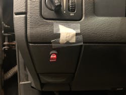
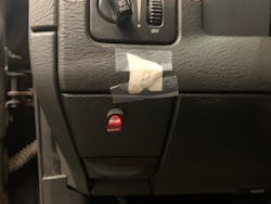
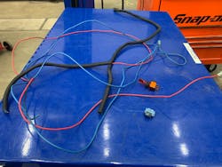
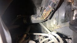
After verifying the complaint of no compressor operation, I decided to perform a quick under hood inspection of the A/C system with my students present. What we found was interesting: a non-OEM power wire Scotch Lock’d to the positive voltage feed terminal of the air conditioning compressor clutch connector. This wire was running through the bulkhead ("firewall") area of the vehicle to a non-OEM single pole/single throw switch, protruding from the dash on the driver’s side of the vehicle (Figure 2+3).
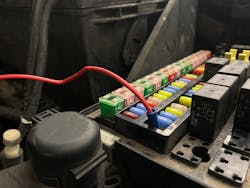
What was even more fascinating about this poor repair was the spade terminal jammed into the under-hood fuse block (Integrated Power Module [IPM]) that always provided unfused power to the inlet of the bypassed air conditioning control switch, crudely mounted in the dash (Figure 4). Knowing that someone paid for such a flawed repair served as a clear calling for my students to perform repairs the correct way.
Step 3: Understanding circuit design
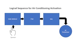
This circuit is module-activated, but requires relay control through the IPM, a request signal from the HVAC module to the PCM, and PCM control for grounding the A/C relay coil circuit (Figure 5). As can be imagined, students in their first few weeks of electrical are just grasping the fundamentals of circuit design, theory, operation, and diagnostics. I wanted to use this problematic vehicle to comfort the future workforce by creating a fundamental strategy, to effectively remedy the concern. They felt the pressure of applying their newly learned skills of reading a wiring diagram, predicting normal circuit behavior, and measuring live variables (voltage and resistance) on this vehicle.
Determining the necessary tools for telling the story:
- How is this circuit activated, and what major components are integrated into this circuit?
- What are our easiest points of access for testing?
- What electrical variables are we searching for?
- What tools will we use to measure the identified variables and diagnose the problem(s)?
When the operator requests A/C function on this vehicle, through the HVAC module, a request is sent to the PCM for verification. The PCM utilizes critical PIDs, such as both low and high-pressure transducer values of the AC system to determine charge status, prevent icing, and protect the compressor from damage during the engagement. The compressor is also an engine load (when activated) and requires PCM controls to supplement the power lost upon activation.
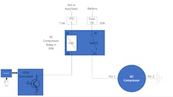
So long as the PCM is content with the critical values, it provides a transistor-activated ground, which energizes the coil of the A/C compressor relay, integrated with the IPM. Through fundamental electromagnetic principles, the relay's internal switch is then closed, creating switched 12-volt power supply through the IPM harness, to pin 1 of the compressor connector. The compressor has a dedicated ground at pin 2 and will allow current flow if power is supplied to pin 1 (Figure 6).
In knowing the previous repair facility provided a supplemental power supply switch, the students had immediate concerns about the original power source being disabled. We performed a visual inspection of the circuit protection devices activated in the IPM but found no measurable flaw.
From this point, we decided to install relay extensions into the IPM to measure activated values going into, and coming out of the A/C, compressor relay as it is the perceivably easiest point of access. Using a DMM with the engine running, we measured source voltage into terminal 30, from the 10A compressor fuse and to pin 85 of the relay coil, from the 7.5A Positive Temperature Coefficient (PTC) “fuse” 1. This indicated an open circuit was not present between the power source, for neither the low amperage coil control circuit nor the higher amperage relay power supply, through the IPM.
From this point, we measured voltage out of relay, at pins 86 and 87. Pin 86, serving as the transistor activated ground from the PCM, displayed 100mV, indicating the PCM ground control had no major concerns.
The DMM value at pin 87 of the relay matched vehicle source voltage, indicating the AC relay was successfully activated, and energy could be distributed through pins 30 and 87, of the relay. This meant the relay switch had continuity but left us questioning if any other circuit problems were present, as the compressor clutch was still not engaging.
If source voltage was available at pin 87 of the relay, but not at the compressor clutch, a few issues could be suspected:
- An open circuit
- A high resistive fault
- A short to ground
If the circuit was open, no current flow would be found in the A/C compressor circuit. If a high resistive fault existed, the voltage would be consumed somewhere between the IPM block and ac compressor ground (aside from voltage dropped on compressor clutch coil). If a short-to-ground existed, the 10A fuse 16 would certainly be open, not allowing voltage to be available to the relay itself.
To dissect this circuit, I had the students use the factory diagram to predict which electrical variable they believed would be best to measure. Knowing how potential faults could impact circuit protection components, they quickly selected ohms and/or a continuity measurement.
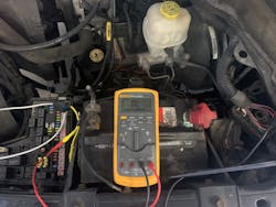
Knowing that industry commonly uses the golden rule of .2 ohms per path of continuity, as an indication of circuit integrity, the students applied this understanding by measuring circuit-off continuity, between pin 87, out of the relay to pin 1, of the AC compressor clutch connector. They found the ever-exciting “O.L”. Through this measurement, they concluded the circuit was open (Figure 7).
So, what’s the fix? Some may prefer a quick fix and recommend bussing pin 87, out directly to the compressor voltage supply circuit. While this is an efficient repair, it provides concerns since the open circuit may encounter other circuits, or provide a short to ground, bypassing the engineered load later in circuit. The preferred method of repair for this vehicle was to locate the measured open, repair the open, and place the vehicle back in service, as built.
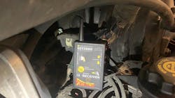
To locate the open, we used the PowerProbe ECT2000, to supply pulsed source voltage through terminal 87 of the relay. This tool relies on both vehicle power and ground to generate a signal, detected by an antenna (Figure 8).
Knowing the IPM harness was tucked alongside the driver's side under hood fender well, then along the vehicle's bulkhead, to the engine control harness, the ECT2000 was practical as it provides some remote distance when checking for circuit faults that may be shrouded with other conductors.
During the inspection, we located the source of the fault: The harness bend at the driver’s side of the air inlet box, along the bulkhead (Figure 9). In removing the harness shrouding and tape, we found the compressor's voltage supply circuit open, by abrasion. To make the immediate repair, we used solder, heat shrink, and a protective layer of electrical tape to the open. We then rewrapped and sealed the harness from the elements and under hood components.
Step 4: Verifying the repair
We removed the crudely installed harness, repaired the damaged power feed wire to the A/C compressor, and returned the harness to its original condition. To determine if the problem was successfully diagnosed and repaired, we reinstalled the airbox, started the engine, and requested A/C (through the HVAC control head). As suspected, the air conditioning compressor activated, cycled, and provided passenger compartment heat exchange effectively.
What fundamentally went wrong with this vehicle during its previous service was a failure to follow through. If the individual who previously installed the A/C compressor bypass switch used the fundamentals of electricity and electronics to test this circuit’s continuity, they would’ve found the same fault fist year, first-semester students could find in a matter of minutes.
Emphasizing the importance of effective methods of testing, and the morality of servicing a vehicle properly, is something I strongly encourage. In knowing that many technicians already have a target on their back based on societal expectations assigned their occupational title, it is critical to develop technicians that understand the problem at hand and effectively deliver.
What we gathered from this fundamental and brief encounter is the effective use of service information for system/circuit theory, wiring diagrams, prediction of normal circuit behavior, the use of a digital multimeter, a quick continuity check, and inspection of the harness provided resolve. Fortunately for my students, this encounter created their first official diagnosis of an electrical fault. I hope it will serve as a reminder of the importance of fundamental electrical theory and tool usage in their future experience.
About the Author
Chris Reynolds
Chris Reynolds is an ASE Master Technician, ASE-Education Foundation evaluation team leader, and an associate professor of automotive technology at Lewis & Clark Community College in Godfrey, Illinois. He is currently in his second year of study toward a Doctor of Education in Educational Practice degree at the University of Missouri – St. Louis. He enjoys time with his wife and three children and advocating for the needs of the automotive service industry and the field of technical education.
