Sensors for current and future vehicle systems: Understanding ADAS sensors, part 1
Content brought to you by PTEN. To subscribe, click here.
The advanced driver assistance systems (ADAS) of today are supported by various sensors and are paving the way toward future automation in next-generation vehicles. You’ve likely encountered these systems where service operations required you to perform additional operations to maintain system integrity to support proper operation. These sensors could include cameras, infrared cameras, lidar (light, detection, and ranging), radar, and ultrasonic sensors. In this two-part article, we will take a closer look at different types of ADAS sensors and discuss how they are used to support ADAS and ultimately, SAE J3016 Level-5, fully autonomous vehicles.
Cameras
For at least the last decade we’ve seen most manufacturers deploy forward-facing cameras on some of their vehicles. The very early systems classified as SAE J3016 Level-0, mainly provided warnings for lane departure and potential collision events with vulnerable road users (VRUs). As computer vision (CV) technology advanced, ADAS became far more capable. CV and artificial intelligence (AI) brought forward artificial neural networks (ANNs) capable of identifying the environment around the vehicle with object detection, classification, body pose detection, semantic segmentation, character recognition, and more, typically based upon industry standard “common objects in context” (COCO) datasets used for training perception networks.
Digital camera basics
A digital camera collects the light rays reflected from objects within the camera’s field of view (FOV) which are passed through a series of concave and convex glass elements that make up the lens. Light rays passing through each layer are deformed in a way so that they are translated onto a flat plane. The flat plane hosts the digital sensor made up of receptor pixels. The light is first passed to the receptors via an array of red, green, and blue filters which are arranged in an out-of-balanced manner where 25 percent are red, 25 percent are blue, and 50 percent are green (Figure 1). Red, green, and blue are typically the primary colors used in digital photography because they are additive colors and the mix of adding these together at various levels allows for the closest reproduction of the images for display.
If the imager has a resolution of 1920x1080, there would be an array of color receptors in the arrangement of about 500,000 red and blue filters and about 1.5 million green filters. From there, each pixel “borrows” the color information from each adjacent color receptor to fill in the other colors. This process is referred to as “bayering.”
The lens elements help to capture the desired field of view (FOV) by the design engineer. This could be an extremely wide area such as required by a single backup camera sweeping up to 180 degrees (Figure 2). This can be classified as the extreme where straight lines are clearly distorted. This is where one level of calibration comes into play which we’ll go into later in the calibration section of this article.
For automotive use, cameras are typically designed differently by eliminating the green filters and replacing them with clear ones. You may see this denoted as RCCB. The reason for this is that the clear pixels allow for better low-light sensitivity and lower noise because the sensor gain doesn’t have to increase as much in such conditions. CV supporting ADAS doesn’t need to see pretty pictures, they just need the appropriate information leading to superior perception of the environment around the vehicle.
ToF cameras — lidar
Time of flight (ToF) cameras typically work by emitting light pulses, typically in the infrared (IR) spectrum which we humans cannot see without special instruments, (see my video covering lidar here: youtu.be/K7NRdwpqaAI) and measuring the time it takes for the light to reflect from an object and return to the camera sensors. With this measurement, along with the speed-of-light time constant, the system can calculate the distance to the object. ToF cameras can be used for a variety of ADAS applications, such as ACC, AEB, and PAEB. They are particularly useful in low-light environments where other sensors may struggle to provide useful information. ToF cameras are becoming increasingly popular in the automotive industry as they provide an efficient and accurate way of providing CV perception. However, these technologies are still rather expensive, but as their costs come down, we’re likely to see more of them in the future. You may have already seen a lidar system on a vehicle passing through your shop. See Figure 3 to see if this looks familiar.
Mono cameras
Mono cameras consist of a single camera that captures images of the environment. The camera's image sensor can detect light, and the camera's processor is able to interpret the data to produce an image. These images are then analyzed by the ADAS system to detect objects, such as other vehicles, pedestrians, and traffic signs. The technology of mono cameras has advanced over the years, which has improved their performance and capabilities for ADAS applications.
For example, early mono cameras used CCD image sensors that provided low-resolution images with poor low-light performance. Nowadays, most mono cameras use CMOS image sensors which provide higher-resolution images and better low-light performance. Additionally, the processing power of mono cameras has also increased, which allows them to perform more advanced image analysis in real time.
Moreover, the use of deep learning techniques within cameras is continuously advancing. This has improved their ability to detect pedestrians, bicycles, and other objects, which is important for ADAS safety features such as AEB, PAEB, and LKS.
Most recently, Honda has been able to remove the radar sensor on some of their vehicles and still achieve the same or better ADAS functionality for ACC, AEB, PAEB, LKS, and more.
Stereo cameras
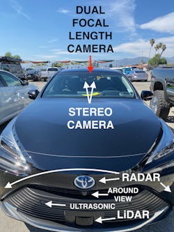
A stereo camera system consists of two cameras mounted side-by-side, typically forward facing, that capture images at the same time. By comparing the images captured, the stereo camera system can calculate the distance to objects in the scene providing depth perception. This is accomplished by using epipolar geometry. The known distance between the two sensors within the camera mounted on the same plane within the camera module can be used to triangulate the distance to the object being observed. Therefore, it is important to properly calibrate the camera following service events calling for those procedures. This information can be used for a variety of ADAS applications, such as ACC without the need for radar, obstacle avoidance, and pedestrian detection. The stereo camera system can also be used to create a 3D map or sometimes referred to as a point cloud of the environment within its FOV, which can be used for navigation and localization. This 3D mapping capability is particularly useful for autonomous vehicles, as it allows the vehicle to understand its surroundings and navigate accordingly. Stereo cameras are becoming increasingly popular in the automotive industry as they provide an efficient and accurate way of measuring distance, which is important for the safe operation of ADAS-equipped vehicles. See Figure 4 showing a 2022 Toyota Mirai equipped with a stereo camera and an array of other sensors.
Sensor calibration is an essential step in ensuring the proper functioning of these ADAS features. Sensor calibration involves adjusting and configuring the sensors to ensure they are providing accurate and reliable data to the vehicle's control systems.
Here are some reasons why ADAS sensor calibration is important:
- Safety: Accurate sensor calibration is crucial for the safety of both the driver and VRUs. Mis-calibrated sensors can lead to deficient system operation.
- Legal compliance: In many countries, sensor calibration is a legal requirement.
- Performance: Properly calibrated sensors can lead to improved ADAS performance.
In summary, performing ADAS sensor calibration is crucial for ensuring the safety of the driver and VRUs. It is important to have the calibration operations carried out by a trained service professional to ensure that it is performed properly.
Camera calibration
Cameras have two basic forms of calibration. The first (intrinsic) involves transforming three dimensions onto a flat plane with accurate representation. One of the challenges is the distortion that occurs as the light rays are passed through each lens element. The easiest way to visualize this, as mentioned earlier, is the viewing of straight lines on the flat image plane. This calibration operation is typically a “one and done” calibration performed at the time of camera manufacturing since it should not change. However, it is possible that there could be corrections applied during field calibration. In photography, higher-end cameras with interchangeable lenses carry calibration data that is then transferred to the camera body when mounted and operated. The calibration information is used to transform the image properly onto the flat plane of the sensor image with little to no distortion. Keep in mind that what you see being displayed may not be the exact data the imaging system is using to accomplish its job as mentioned earlier.
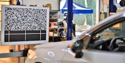
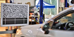
The second type of calibration is called extrinsic. Extrinsic basically means external and how the camera placement on the vehicle is in relation to a known datum point (usually vehicle centerline) to its field of view. If the calibration routine is classified as static, this means that there will be a requirement for a special target(s) to be placed in specific coordinates within the camera’s FOV (Figure 5). Many of the modern tools today provide efficiency gains with target placement operations as they relate to specific vehicle data points.
This is very important to understand because if the system does not have a solid relationship between the camera view and the known datum point on the vehicle, then any of the warnings or corrective actions issued on an ADAS-equipped vehicle could have negative consequences. What this comes down to is that if there are changes to the vehicle ride height, steering/suspension geometry, or body-to-chassis changes, then calibration operations should be considered by referencing the appropriate service information (SI). In some cases, you may not find direct statements within SI telling you that if you perform operation 'X' then you must do 'Y'. However, you may want to adopt a policy of your own. It all comes down to liability, and if you look from the courtroom perspective where the judge is looking at an owner’s manual statement claiming that the AEB system may not work if the wheels are misaligned on a vehicle you aligned, and asks you why you didn’t perform a recalibration on the camera when you, as the automotive service professional, knew that there is a relationship between the vehicle geometry and camera, you may be found at fault if you did not carry out the procedure. To date, I haven’t been made aware of any such events I described above but they cannot be ruled out from happening.
Conclusion
Many service operations carried out today may require additional operations to be performed that relate to ADAS. Be sure to reference up-to-date service information to ensure that complete repairs are being performed on your client's vehicles. Returning a vehicle to service in proper operating order is an essential step today, especially with all the active safety systems being deployed on vehicles.
In part two of this series, we’ll dive into infrared cameras, radar, and ultrasonic sensors and some of the lessons learned during the service and repair of these systems.
ADAS Acronyms
ACC - Adaptive cruise control
AEB - Automated emergency braking
BSW - Blind spot warning
CTA - Cross-traffic alert
LCA - Lane change assist
LDW - Lane departure warning
LKA - Lane keeping assistance
PAEB - Pedestrian automated emergency braking
RAEB - Rear automated emergency braking
RCTA - Rear cross-traffic alert
TSR - Traffic sign recognition
About the Author

Scott Brown
Founder - Diagnostic Network
Scott is an ASE Master Certified Automobile Technician with L1, L3, & L4 credentials and has over 39 years of professional service industry experience. As an independent shop owner in Southern California and with his engagement at various levels of within our industry, he continuously strives to move the industry forward through networking, education, communications, and training. Scott is a founder of the Diagnostic Network (https://diag.net/) which was born in 2018 after he retired after 22 years at iATN, where he served as company president.
Brown is also the host of Professional Tool and Equipment News (PTEN) and VehicleServicePros.com podcast, Torque Factor. The podcast addresses the latest automotive service technologies while focusing on expanding knowledge and awareness around tools, equipment, education, and industry trends.


