A good friend of mine, Michael, was recently faced with a 2007 Ford Edge experiencing a misfire under certain driving conditions. After some preliminary data evaluation, he hypothesized that the drivability symptom stemmed from a fault in the vehicle’s ignition system.
By systematically placing the vehicle’s engine under sustained load, the misfire fault would present itself readily and always seemed to occur on cylinder No. 2. Considering the ignition system’s configuration, it was not prudent to swap the coils from cylinder to cylinder (a common technique to see if the misfire fault moves along with the coil). The coils of bank No. 1 reside under the intake manifold (Figure 1).
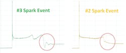
With the idea of an ignition system fault in mind, Michael monitored the suspect coil’s control circuit with a digital storage oscilloscope (DSO), along with a non-suspect coil for comparison (Figure 2). After capturing the data during the misfire condition, the only anomaly Michael noticed was a difference in the coil-oscillation section of the ignition event.
It seems (whether the misfire was present or not) that the coil oscillations are missing from the suspect coil’s ignition event. Two questions come to mind:
- What do the missing coil oscillations mean?
- Is it the cause of the misfire?
Preliminary data
This is where Michael reached out to me to evaluate the ignition events and see if I could offer some insight. Again, a coil swap is just what the doctor ordered but considering the coils reside beneath the intake manifold, it is not a gamble worth taking at this point. Let's see what the data has to offer us (Figure 3).
The ignition event occurs because of a transfer of energy. But this energy is derived from magnetism.
A magnetic field is created when electrical current flows through the primary windings of the ignition coil.
However, the magnetic field that develops over time (what we refer to as “dwell”) must dissipate instantaneously when the electrical current stops flowing through the primary windings of the ignition coil. When that occurs, and through the function of the step-up transformer (the ignition coil, itself) a spark should discharge.
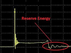
This spark contains a finite amount of energy. A properly designed and properly functioning ignition system should produce a spark not only capable of igniting the air/fuel (A/F) mixture under all operating conditions; there should be some reserve energy remaining. This reserve energy will be seen dissipating as coil oscillations, ringing out over time (Figure 4).
The data doesn’t lie
With all the information in front of us, and the desired information not yet obtained, we are faced with deciding how to proceed. Here are some bullet points of what we know to be factual, and I will ask all of you, diligent readers, for your input:
- The No. 2 cylinder misfires under load
- Preliminary data points to an ignition system fault
- Comparative ignition captures show a variation in the coil oscillations between cylinders
- The coils are housed under the intake manifold
Given this information, what would you do next?
- Replace all six ignition coils
- Replace the No. 2 ignition coil only
- Commit to intake removal and swapping coils for diagnostic purposes
- Obtain a common amperage waveform of all coils
SOLVED: (December 2023, Motor Age) 2013 Honda Crosstour, “check gas cap” message
What would you recommend doing next, given the data bullet points in last month’s challenge?
Given this information, what would you do next?
- Smoke test the EVAP system
- Replace the fuel cap because it’s inexpensive
- Replace PCM
- Monitor FTP, vent solenoid, and purge valve with a lab scope during failure
For those of you who chose answer No. 4, congratulations! According to the data, smoke testing EVAP system would not yield any leak. The FTP sensor signal remained stable under natural vacuum testing conditions. These conditions are a lot more stringent than a smoke test, meaning, if the natural-vacuum test passes, the EVAP system will most likely pass a smoke test. For this same reason, replacing a fuel cap due to low cost would still be foolish because a leak is not present.
Although replacing a PCM may be the correct step (assuming there was a logic error), doing so is premature because there are still unanswered questions. Monitoring the FTP, vent solenoid, and purge valve simultaneously with a lab scope will not only verify the functionality of the components working as a system but will also demonstrate the failure when it occurs.
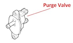
The purge solenoid was the root cause of the fault (Figure 5). At times, it would fail to seal during monitor criteria conditions. A DTC never set because this component would never fail during the natural-vacuum leak detection that occurred during key-off testing conditions. This fault would only occur on the road (when the engine compartment was hot).
Be sure to read April's Motor Age issue for the answer to this month’s challenge and what was discovered!
About the Author
Brandon Steckler
Technical Editor | Motor Age
Brandon began his career in Northampton County Community College in Bethlehem, Pennsylvania, where he was a student of GM’s Automotive Service Educational program. In 2001, he graduated top of his class and earned the GM Leadership award for his efforts. He later began working as a technician at a Saturn dealership in Reading, Pennsylvania, where he quickly attained Master Technician status. He later transitioned to working with Hondas, where he aggressively worked to attain another Master Technician status.
Always having a passion for a full understanding of system/component functionality, he rapidly earned a reputation for deciphering strange failures at an efficient pace and became known as an information specialist among the staff and peers at the dealership. In search of new challenges, he transitioned away from the dealership and to the independent world, where he specialized in diagnostics and driveability.
Today, he is an instructor with both Carquest Technical Institute and Worldpac Training Institute. Along with beta testing for Automotive Test Solutions, he develops curriculum/submits case studies for educational purposes. Through Steckler Automotive Technical Services, LLC., Brandon also provides telephone and live technical support, as well as private training, for technicians all across the world.
Brandon holds ASE certifications A1-A9 as well as C1 (Service Consultant). He is certified as an Advanced Level Specialist in L1 (Advanced Engine Performance), L2 (Advanced Diesel Engine Performance), L3 (Hybrid/EV Specialist), L4 (ADAS) and xEV-Level 2 (Technician electrical safety).
He contributes weekly to Facebook automotive chat groups, has authored several books and classes, and truly enjoys traveling across the globe to help other technicians attain a level of understanding that will serve them well throughout their careers.


