The formation of the Toyota New Global Architecture (TNGA) is aimed to streamline production and development across all of Toyota's automotive manufacturing. The results of TNGA have led to a dramatic reduction in engine platforms from over 800 variations to fewer than 20. Alongside TNGA, Toyota introduced the Dynamic Force Engine family, featuring I3, I4, and V6 engines with turbo and non-turbocharged applications.
Toyota's Dynamic Force Engine prioritizes thermal management to enhance efficiency and reduce emissions. Techniques include high-speed combustion technology, a variable cooling system, continuous variable capacity engine oil pump, and an electrically controlled variable intake camshaft phaser. These innovations aim to maximize energy extraction from gasoline fuel injected into the engine.
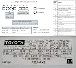
The Dynamic Force Engines also introduced a notable change in Toyota's engine naming nomenclature, integrating engine displacement between a two-letter code. For example, the A25A signifies a 2.5-liter engine.
This article focuses on the A25A-FKS engine, with its remarkable thermal efficiency of up to 40%. Its hybrid counterpart, the A25A-FXS, achieves an outstanding 41% efficiency, surpassing traditional internal combustion engines typically running at around 35%. But please note that almost all of these technologies are used across the entire Dynamic Force Engine family.
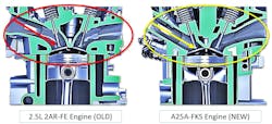
A25A Dynamic Force Technology: Revised Intake Design. The Dynamic Force Engine has several notable intake port and cylinder head design modifications from its predecessor 2.5L four-cylinder engine design. These were needed to produce a strong, tumbling air flow into the cylinders enhancing high-speed combustion, boosting engine power output and fuel efficiency while reducing exhaust pollutants.
The strong tumbling air motion used to accelerate the combustion process has been achieved by widening the angle between the intake and exhaust valves, from approximately 23 degrees to approximately 40 degrees. This allows for a straighter intake air flow. Wider valve angles are used to enhance the air tumble motion and lower the air flow resistance for more effective combustion. But a wider valve angle isn’t the only change to the intake port design. The intake valve seat is now laser clad. By using a process known as "laser cladding," a laser beam is used to melt a copper-based alloy powder into the aluminum cylinder head. This creates intake valve seats that are directly integrated to the cylinder head. These laser clad intake valve seats are considerably thinner than the traditional press-fit intake valve seats, and they improve intake valve cooling, increase wear resistance, and permit the intake port to have a more ideal size and shape. Traditional press-fit valve seats are still used for the exhaust valves.
A25A Dynamic Force Technology: PCV Integrated Into Cylinder Head. The PCV valve is mounted in the cylinder head, between the intake manifold (the intake manifold incorporates the crankcase ventilation circuit) and cylinder head to regulate temperature and lower the possibility of valve freeze-up. An external oil separator is mounted on the block under the intake manifold.
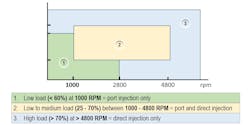
A25A Dynamic Force Technology: D-4S Fuel Delivery System. Toyota uses the D-4S fuel system to supply fuel to the A25A Engine. This system combines both a Port and GDI fuel injection system. To provide the best fuel mixture in the cylinder under the most operational situations, both sets of injectors collaborate. The engine's particulate matter emissions were significantly reduced by using both port and direct fuel injection and exhaust emission reductions were a major factor in the engine's development. The purpose of the port fuel injectors is to supply fuel to the engine within a designated operating window and are not intended to clean the intake valves. The long 10-point spray low-pressure port fuel injectors have a modified plug that differs from the conventional Bosch standard injector plug of the past. The six-hole GDI fuel injectors have been updated for improved fuel aiming (angled toward and across the piston) and placement in the cylinders, but they work exactly like any other direct fuel injection system. By using this revised spray pattern, valve interference has been reduced, enabling high-pressure atomized spray to better enter the combustion chamber independently of airflow. This injector design makes the fuel more evenly distributed, which helps it mix better with the air coming in, which leads to better burning no matter what the driving conditions are like.
To achieve stricter emission control levels, the Powertrain Control Module (PCM) now only partially lifts or partially opens each GDI injector during an injection pulse, when the engine is cold or warming up. Full injection GDI lift resumes at normal engine temperature. This method significantly reduces combustion chamber particulate matter by 60% over the prior engine design.
The PCM times the port and GDI injections during a cold start to reduce emissions and stratify combustion. To accomplish a stratified combustion process, the PCM regulates the timing of the port and direct fuel injectors during a cold start. Right after a cold engine start, fuel is injected into the intake port during the exhaust stroke, and after the compression stroke, the GDI injector injects fuel, creating a stratified air-fuel mixture. The area around the spark plug will be richer than the rest of the combustion chamber. This late injection procedure allows for retarded ignition timing, which raises exhaust gas temperature and accelerates catalyst warmup.
The PCM will cycle both the port and the GDI injectors occasionally while at idle and there will be an audible change in the engine’s sound as this happens. This is most notable if the technician has the engine decorative/ noise deadening cover off the top of the engine in the shop. This is a normal operation, used to flush the hot fuel from the GDI injectors and high pressure GDI pump.
A25A Dynamic Force Technology: Variable Flow Cooling System. Conventional mechanical coolant pumps, which are powered directly by the engine, consistently circulate coolant when the engine is in operation, even when cooling is not needed. By implementing a variable flow cooling system, Toyota has been able to reduce friction, enhance engine warm-up capability, and lower fuel consumption.
The system uses an electric coolant pump and other coolant flow controls controlled by the PCM. This cooling system design ensures ideal coolant flow and volume. It will support a specific engine temperature, regulate heater core output, and flow to the Automatic Transmission Fluid (ATF) heat exchanger. And it can do this under the entire range of operating conditions, even when the engine is off. (The Dynamic Force Engine has a hybrid version, and the non-hybrid does have Toyota's “Smart Stop Technology,” so these engines can be stopped frequently.)
During the first phase of a cold start, the electric coolant pump may not pump any coolant, as the PCM will decide what coolant flow is needed. This enables the engine and the catalytic converter to reach the ideal temperatures more rapidly. For improved heat transfer, the coolant and engine oil internal passages are cast closely together. This design provides quicker engine warmup and improves engine cooling in high-load scenarios.
The thermostat that regulates the operating temperature of the cooling system has also been upgraded within the Dynamic Force Engine architecture. The A25A and other engines in the Dynamic Force family are using a mapped thermostat enabling the PCM to regulate the operating temperature. The PCM will provide a duty cycle control to the thermostat assembly. This can accelerate the opening process by heating the wax, which in turn causes expansion. This allows for improved flow when the engine load demands it.
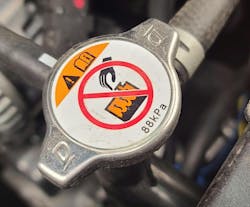
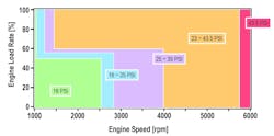
This control enables the thermostat to regulate the circulation of the coolant in the engine cooling system with more precision. The mapped thermostat in the A25A opens at a temperature of 176 degrees to 183 degrees which is approximately 10 degrees cooler than the typical previous four-cylinder engine. It should also be pointed out that this cooling system is a low pressure system, with an expansion tank cap pressure of 12.75 psi (88kPa).
The variable flow cooling system also has two Flow Shutting Valves (FSV) that scan tools may call Coolant Water Routing or Coolant Switching Valves. These coolant control valves control the coolant flow through the heater core (FSV1) and the ATF warmer/cooler (FSV2). The FSV valves have a unique magnetically controlled operation to control coolant flow. When the PCM applies power to them they will become magnetized and close.
The variable cooling system of the A25A engine allows for four distinct cooling system modes of operation.
- Early Warm Up: To warm up to operational temperature faster, the Early Warm up mode stops coolant flow to the heater core and ATF warmer. Coolant will still flow through the block, cylinder head and EGR cooler.
To minimize piston slap during warmup, the flow rate reduced. - Heater Priority: To improve heater efficiency, the heater priority mode lets coolant pass to the heater core while preventing flow to the ATF warmer.
- Output Enhancement: This is applied when there is a high engine speed and load. The mapped thermostat will open faster and both FSVs will be opened for optimal coolant flow and heat transfer for high-performance cooling and engine knock prevention. The PCM-controlled electric water pump speed will be adjusted for best heat transfer and coolant flow.
- Max Cooling: In this mode, the heater core FSV is closed, like the old cable or motor-operated heater control valve, to enhance air conditioning evaporator efficiency.
The variable electric water pump, the mapped thermostat and both FVS valves are being continuously monitored by the PCM for issues, and that means they are going to be able to set DTCs. Electric water pump DTCs can be set for opens, shorts, no signal, actuator stuck and pump overspeed. It should also be noted that some cooling system failures (water pump and FVS issues) may cause the vehicle to go into a limp-in or failsafe mode and will limit the engine’s rpm to protect itself.
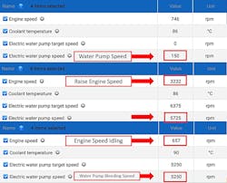
If the cooling system is serviced or drained, there is a special coolant fill procedure that must be followed to ensure that the system is properly bled. This procedure is not activated with a scan tool, but a scan tool is needed to show the tech that the Engine Coolant Mode has been entered by observing the water pump speed (water pump speed will be increased to approximately 5,250 rpm and both FVS valves will be opened).
The engine cooling fill procedure:
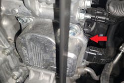
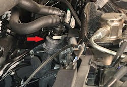
- Disconnect the quick connect water hose on the EGR valve assembly.
- Slowly fill the radiator until coolant appears at the EGR valve.
- Reinstall the quick connect water hose on the EGR valve.
- Ensure the coolant level is correct in the rad and expansion tank and install the coolant caps.
- Perform the Engine Coolant Filling Mode procedure to complete the bleeding procedure. Enter the Engine Coolant Filling Mode as follows.
- Place the shifter in park.
- Start the engine and run the engine at 1,500 rpm for 15 seconds or more.
- Check the speed of the electric water pump on the scanner. It should increase in speed when the engine speed is raised to 3,000 rpm for 10 seconds and then let the engine idle.
- Repeat the procedure three times.
- Once the Engine Coolant Filling Mode is entered you will see a sudden shift in the water pump speed.
- NOTE: The vehicle will typically enter Engine Coolant Filling Mode the first time the engine is revved to 3,000 rpm. You must watch the water pump speed on the scan tool data.
- Turning off the engine will exit the Engine Coolant Filling Mode. After exiting, verify the coolant is at the correct level.
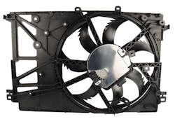
A25A Dynamic Force Technology: Cooling Fan Control. A single motor, variable speed assembly cooling fan with a communications line to the PCM is used to manage the cooling fan operation, replacing the earlier twin cooling fan assembly. A high-powered brushless fan motor is used, enhancing cooling performance, while reducing the assembly’s weight. The motor is equipped with an integrated PWM controller that allows for precise control of the motor's rotational speed while maintaining a small and lightweight design. The cooling fan blades have a unique shape, which allows for quiet, even airflow. An active shutter system is also a part of the cooling system.
A25A Dynamic Force Technology: Variable Displacement Oil Pump: An electronically controlled variable displacement oil pump is used on the A25A engine. By adjusting engine oil pressure and volume in response to engine oil temperature, rpm and engine load, this oil pump minimizes friction, while maximizing lubrication.
The PCM regulates the system using an oil control switching valve, and the oil pump is a Trochoid Design. The PCM can smoothly adjust engine oil pressure between minimum and maximum using this oil pumping system to meet the engine's requirements. When a low oil output volume is needed, the oil control switching valve is activated by the PCM. This raises the pressure inside the control chamber of the oil pump, reducing the size of the pumping chamber by forcing the outer-driven gear closer to the inner drive gear. This will reduce the volume of oil the pump can pressurize, lowering the engine oil pressure. To increase the engine oil pressure the PCM will lower the pressure inside the control chamber of the oil pump. An integral spring will force open the control chamber, increasing the size of the pumping chamber, increasing the oil pump’s volume, raising the engine oil pressure. This is also the default position of the control chamber if the oil control switching valve fails, or the wiring to it becomes damaged.
The A25A uses piston cooling oil jets to reduce friction and maintain piston temperature to reduce engine knock. By controlling the engine oil pressure with the variable displacement engine oil pump, these piston cooling oil jets will only be activated when the oil pressure is increased, and piston cooling is needed. When the engine is cold, and the oil pressure is lower, the piston cooling jets aren’t functional, allowing for better piston warmup and reducing piston noise.
Use of the proper engine oil viscosity is required. Incorrect engine oil viscosity can set fault codes for low pressure in three stages: minor, moderate, and severe. The PCM can even limit the engine's rpm, acting as a failsafe to protect itself if the oil pressure is too low.
A25A Dynamic Force Technology: Cooled EGR Assembly. Before the EGR gas passes through the EGR valve, it is directed through the cylinder head and into an EGR cooler to cool it. The cylinder head has molded fins in the EGR passage to maximize surface area, which helps with heat transfer in two ways: heating the cylinder head to quickly warm a cold engine and cooling the EGR gases. When the engine is cold, the EGR valve will be activated, routing EGR gases through the cylinder head to warm the engine faster.
A25A Dynamic Force Technology: Variable Timing VVT-iE. A DC brushless electric motor is used by the VVT-iE to regulate the phasing of the intake camshaft. This allows for precise intake camshaft phase control at low engine speeds or low engine temperature because it is powered by an electric motor not engine oil.
Depending on the engine operating conditions, the PCM can accurately adjust the VVT-iE electric motor's rotational speed and direction to adjust the intake camshaft phase to the desired position. This enables a broad control range over the power spectrum and enables Atkinson cycle engine operation.
Toyota's Dynamic Force Engine's use of multiple variable systems and careful engineering dramatically improves this engine’s thermal efficiency.
Using high-speed combustion, an enhanced intake design, a variable flow cooling system, a variable engine oil pump, variable intake camshaft phasing, D-4S fuel delivery, PCV integration, and a cooled EGR assembly collectively enhance engine efficiency while reducing emissions. Toyota continues to innovate in automotive engineering, and their commitment to combustion optimization and environmental sustainability shows their dedication to producing reliable, high-performance engines.
About the Author

Jeff Taylor
Jeff Taylor is a seasoned professional at CARS Inc. in Oshawa with 40 years in the automotive industry. As a skilled technical writer and training developer, he holds licenses in both automotive and heavy-duty vehicle repair. Jeff excels in TAC support, technical training, troubleshooting, and shaping the future of automotive expertise.
