Mastering modern engine diagnostics: Techniques and tools
Over the past 40+ years in this industry, I have seen an amazing technology tear being applied to automobiles. Back in my beginnings, we did not have any advanced engine controls such as variable cam timing, variable lift, and variable length intake runners. Neither did we have the tools and equipment to analyze these advanced systems. However, some of the same tools we used back then are very much relevant today. In this article, we will review what is different today and share methods that can be effectively applied today. In conclusion, I believe that you are going to learn a thing or two, so let us get started.
OBD-II advancements
On-Board Diagnostics II (OBD-II) has become a great standard of vehicle diagnostics since its introduction in the mid-1990s. Today, advancements in OBD-II systems have significantly enhanced today’s diagnostic technicians:
- Enhanced communication protocols: Since around MY 2008, the CAN (Controller Area Network), which allows for faster and more reliable data transmission between vehicle systems and diagnostic tools, has been an excellent value add.
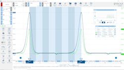
- Increased data acquisition: Modern vehicles generate a vast amount of data. Understanding how to read and interpret this data is crucial. OBD-II systems now include a broader range of parameters that can be monitored in real-time (Figure 1).
Parameter IDs (PIDs)
Parameter IDs or PIDs are essential for accessing specific data from the ECU. Here is a look at how they have evolved:
- Standard vs. proprietary PIDs: While standard PIDs are universal across vehicles, manufacturers often implement proprietary PIDs for added diagnostics. Knowing these can offer deeper insights into vehicle-specific issues.
- Real-time data: Advanced PIDs allow for monitoring dynamic engine parameters, which are vital for diagnosing intermittent issues or conditions under various driving scenarios.
- Mathematical PIDs: There may be cases where you are looking to perform math operations on one or more PIDs. Some scan tools will allow the end user to construct such PIDs. Later in this article, I will demonstrate this.
3-byte DTCs
Diagnostic Trouble Codes (DTCs) have expanded from 2-byte to 3-byte codes in modern vehicles to accommodate the growing complexity:
- More specific diagnoses: The third byte adds a failure mode indicator. This has provided some relief for an ever-shrinking diagnostic byte storage area. With this, you may see DTCs being recorded outside of their respective PCB or U designations because of space constraints.
OBDonUDS
Unified Diagnostic Services (UDS) is now being adopted and will be the standard in the near future. This communication protocol will allow for more comprehensive diagnostics. UDS operates on 2-byte Data Identifiers (DIDs) as compared to 1-byte PIDs. This allows for up to 65,535 DIDs as compared to 255 PIDS. Error reporting will become more robust as well since this new standard is a significant step change for diagnostics. Expect to see more on this topic in the future.
Basic tools and testing techniques
Before we talk about tools, we need to ensure that our knowledge is at the level of competency to ensure that test results can be applied effectively to form a strong hypothesis and diagnosis. With today’s engine control systems and features able to affect cylinder fill, we need to confirm engine cylinder compression balance and have a strong understanding as to how it can be either negatively or positively affected. Compression testing should be one of the top priority tests when addressing many engine performance complaints. Now this does not necessarily mean that we need to remove all spark plugs and test each cylinder separately every time, as there are tests that can be performed with ease to help get the technician on the right path.
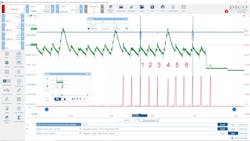
The following vehicle is a 2017 Chrysler Town and Country with a 3.6L ERC engine with variable valve timing for both intake and exhaust camshafts and variable valve lift and duration for the intake valves only. The vehicle arrived with a P0304 – Cylinder 4 Misfire and a P105C – Intake Valve Stuck In Low Lift. A clear flood cranking relative compression test was performed, and there was clearly an erratic cranking rhythm. An oscilloscope was connected to collect the starter motor cranking current along with a cylinder reference (Figure 2).
As you can see, cylinder 4 has a much higher load against the starter. Next, we went in-cylinder and compared cylinder 4 against cylinder 2 where we could clearly see that the #4 intake valve was on the wrong camshaft lobe as the DTC clearly identified. This engine utilizes a special rocker arm with two followers, and the issue here was that the high lift follower was worn and closed the low lift lobe clearance preventing the lockout pin from engaging.
Scan tools
A scan tool can provide great assistance, but each has its strengths and weaknesses. A technician armed with this knowledge will be on track to use this knowledge when faced with a diagnostic challenge. The best tool for the job is the one that can provide the information to the technician they need to make an informed decision.
- OBDII basics: On-board diagnostics is just that, the testing going on in the background on these vehicles can produce a ton of information. Take Mode$06 and Mode$09. Each can provide insight into monitored systems and provide insight on vehicle behavior and performance. If you are weak in either of those two, you may be wasting valuable time when trying to diagnose today’s vehicles.
- Enhanced functionality: Many vehicle manufacturers have extended their vehicle test routines way beyond the legislated OBDII requirements. These enhancements have been designed to help the technician make informed decisions. Learning how to use these features can improve your ability to assess and diagnose today’s complex machines.
- Portability and connectivity: Many of these modern tools can be used by connecting them to cloud services for remote diagnostics, coding, programming, and other services.
Software updates
- Firmware updates: Regular updates ensure compatibility with the latest vehicle models and ECU software versions. There may be improvements made to the software that did not necessarily receive full documentation on what was corrected. I believe in doing what I can to ensure that the vehicle has the latest version of what the OEM has made available to the vehicle under test.
- Diagnostic software: Subscription-based models for diagnostic software provide ongoing access to new tool features, bi-directional controls, DTCs, data PIDs and more. The software is never 100% complete and requires ongoing maintenance and updating. Understanding how to properly report bugs can be mutually beneficial. Some companies really listen to their customers and can incorporate changes the market demands.
Diagnostics
A diagnosis can only be arrived at after proper testing and result interpretation. Rarely can a diagnostic conclusion be made from a DTC alone. Case in point. A vehicle may arrive for a P0455 which means that there is a gross leak in the monitored evaporative fuel system. Meaning from the gas cap to the purge valve and everything in-between could be at fault. Although this could be as simple as a loose filler cap, proper steps should be taken to ensure that the system is addressed accordingly.
A technician well versed in EVAP systems will want to assess the system by first understanding how the system is configured and designed for operational validation. For example, does the system use a pump for leak testing or does it use other methods? In many cases, the purge, vent valve and a low-pressure sensor are used by the diagnostic system to assess leakage. In such a system, the technician can monitor purge and vent valve control along with system pressure to understand a little more about what is happening with the system.
In some cases, the diagnostic software may offer an automated test exercise to verify system operation. Toyota’s Global TechStream Plus is an application we use in our shop and offers this test routine (Figure 4).
I find it valuable to run this test prior to making any repairs and then of course running it after issuing repairs and using comparing the results. We will typically include and share these results with the client by embedding them within the repair order.
Turbo / Boost Errors
P0299 – Turbocharger/Supercharger “A” Under boost Condition is a DTC you may have encountered in the past. In my experience with GM platforms, I have seen quite a few of these faults. When you review the diagnostics on this DTC, the analysis the ECM is performing is complex. What I have found is that you can set up a scan tool to display data and evaluate it in the same way that the ECM is judging this data. The tool I’m using in this example is the VCM scanner from HPTuners.
If you’re not familiar with this software, don’t worry, we’ll walk through this. Additionally, you should also be aware that GM has openly published the diagnostic data I am using here:
https://gsitlc.ext.gm.com/gmspo/mode6/index.html
This can be found by going to the ACDelco Technical Delivery System: https://www.acdelcotds.com/
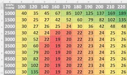
Reviewing the data within these documents you will find details around the diagnostics and failure thresholds for various faults. Focusing on the P0299 Under boost code for the 1.4L RPO:LUV engine I found the following table: See figure 5.
The table rows are populated by RPM and the columns are “Desired Boost.” I took these values and created an Excel table that makes this a little easier to look at (Figure 6).
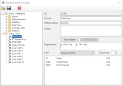
So, the next thing we need to do is create a mathematical pid that provides the “error.” In some cases, the data list on a vehicle may provide you with this information. However, if that information isn’t available, we can create it by using the following PIDs:
- Desired Boost
- Actual Boost
Looking at Figure 7, we are taking Desired Boost and subtracting the Actual Boost value and creating a new PID called Boost Error.
Now when we are ready to scan and data log, we’ll need to make sure that we have at least the following PIDs to make use of this.
- Engine Speed
- Desired Boost
- Actual Boost
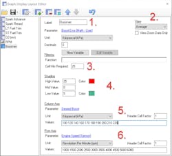
To create the chart to display this data, here’s the setup listed in Figure 8.
- Graph name and PID selection
- View = Average
- You can define how many cell records are collected before the cell begins populating with data
- Control the data shading – adjust as desired
- Column Data – Select the appropriate PID and set values
- Row Data - Select the appropriate PID and set values
Now you are ready to road test and collect data.
One of the approaches I’ve used with success in the past when evaluating under boost conditions on automatic transmission vehicles is to place the selector in manual mode and upshift into fifth gear when possible and try and populate the 160–180kPa desired boost modes at the lower rpms by manipulating the throttle. You will likely want to take an assistant on the road with you to help monitor the data. Then from there, you can work on the higher rpm regions.
Once you’ve completed your road test, it’s time to review.
The following charts are from a vehicle with a leaking wastegate valve and display the MAX, MIN, AVG, and COUNT (Figures 9, 10, 11, 12).
The chart in Figure 13 shows the performance of the new replacement turbo.
Conclusion
The landscape of engine diagnostics is continuously evolving. Staying updated with the latest tooling, understanding how to leverage diagnostic techniques, and mastering the interpretation of complex data is crucial. Whether you're a seasoned technician or new to the field, embracing these advancements is key to diagnosing modern engines with unprecedented precision and efficiency.
About the Author

Scott Brown
Founder - Diagnostic Network
Scott is an ASE Master Certified Automobile Technician with L1, L3, & L4 credentials and has over 39 years of professional service industry experience. As an independent shop owner in Southern California and with his engagement at various levels of within our industry, he continuously strives to move the industry forward through networking, education, communications, and training. Scott is a founder of the Diagnostic Network (https://diag.net/) which was born in 2018 after he retired after 22 years at iATN, where he served as company president.
Brown is also the host of Professional Tool and Equipment News (PTEN) and VehicleServicePros.com podcast, Torque Factor. The podcast addresses the latest automotive service technologies while focusing on expanding knowledge and awareness around tools, equipment, education, and industry trends.


