How a missing crankshaft dowel pin led to a no-start condition
Content brought to you by Motor Age. To subscribe click here.
What you will learn:
•How timing signals determine injector firing time and sequence
•How to use a lab scope to determine camshaft timing without engine disassembly
•How to use a lab scope/pressure transducer to prove engine mechanical integrity without disassemblyI was called to a shop for a no-start on a 2011 Suzuki 2.4 L (Figure 1) that had a rebuilt engine installed. The original engine ran fine but had high mileage on it, along with oil consumption issues. It was not hard to pull the engine as it was only a small four cylinder. The shop was incredibly careful to remove the engine and then reinstall it in reverse order.
The engine was original to the vehicle, and it was completely disassembled and reconditioned back to factory specifications by a local engine rebuilder. The owner of the vehicle took this option because the shop had a tough time finding a rebuilt engine for this particular vehicle. During the process of removing and replacing an engine, anything can happen, but the shop had exhausted all avenues into figuring out why the engine would not start so they called me in to diagnose the vehicle.
My initial encounter
When I arrived at the shop, I decided to do some basic testing to determine which direction to take my diagnostic routine. I placed a spark tester on one of the ignition coils to see if the engine had spark. On the initial crank, there was a momentary spark. It was as if the engine computer was trying to fire the coil but was unable to continue the process. The ignition coil was a coil-over-plug (COP) design and was supplied with power, ground feed, and a signal trigger to control its built-in igniter circuit. The power and ground feeds to the ignition coil were all good, but I needed to hook up my scope to see what (if any) triggering was being supplied to all the coil/igniter assemblies.
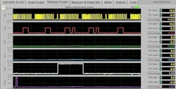
I set up my eight-trace scope to use five channels and monitored these signals as follows:
YELLOW= CKP signal
RED= CMP signal
GREEN= Coil #1 control circuit
BLUE= Coil #2 control circuit
WHITE= Coil #3 control circuit
PURPLE= Coil #4 control circuit
On initial cranking of the engine, you could see that the crank and cam sensor signals had good amplitudes (5V toggling without any dropouts) but the coil igniter triggers were erratic (Figure 2). The green and blue traces had no activity. Although the time base is not indicated in the capture, the white trace had a trigger time of about 196ms, while the purple trace had about 10ms of trigger time. This was very unusual, as it only takes about 4-6ms seconds to saturate an ignition coil on most vehicles. This, from my experience, was a computer that was very confused as to when to start a timing sequence, and at the same time does not know when to turn off the trigger duration times properly.
This could have been an issue with the engine computer itself or an erratic cam or crank sensor signal output but the fact that this vehicle ran before, and the clean sensor outputs had me leaning towards a timing issue. The engine shop that rebuilt the engine was a high-quality shop and I have heard many good reviews about their workmanship, but things can happen.
Ruling out engine mechanical integrity
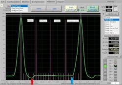
I needed to prove this timing issue, so my next option was to place a pressure transducer in the combustion chamber just to get a glance of valve timing within the cylinder. I removed the spark plug and went ahead and placed a pressure transducer in cylinder #1 and grabbed a waveform (Figure 3). The value of a pressure transducer gives you a great visual representation of what is happening in the chamber, as the valves are opening and closing. I was able to see that the exhaust valve was indeed opening within a common spec time of about 45 degrees F before-bottom-dead-center (BBDC) of the power stroke (Figure 3 red arrow). I also noticed that the intake valve closed within a common spec of about 70 degrees F after-bottom-dead-center (ABDC) of the intake stroke, as the piston started its journey upwards on the Compression stroke (Figure 3, blue arrow).
This was conclusive proof that the cam timing was within specification but there is still another part to this equation that is critical when it comes to computerized ignition timing events. The crank and cam sensor signals need to be of the correct pattern and with the proper orientation to one another. I had good clean crank and cam sensor waveform patterns with good amplitude, but I had nothing to compare them with. I had to leave the shop and go searching on the Internet to find a known-good pattern (of the same year vehicle, with the same engine).
This was the original engine, but I was not certain if the trigger wheels within the engine were changed because I had no direct information on what was done in the rebuilding process. This led me to speak with the rebuilder at the engine facility as well.
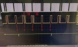
After about a week of searching on a few sites and posting for access to getting a known-good waveform, I struck gold. A fellow technician alerted me to a website of a diagnostic company in Eastern Europe. This technician had the waveform I needed on his website library of acquired signal patterns from many different vehicles. One of them is for a Suzuki Grand Vitara with a 2.4L engine (Figure 4). You could see that the crank sensor pattern was 1-13-16 in tooth patterns of one revolution of its shaft and the cam sensor pattern was 1-1-2-2 of tooth patterns in one revolution of its shaft. These patterns matched identical to what my patterns were showing but my patterns were out of synch. The known-good pattern showed the first “1” tooth of the cam trigger was lined up with the single “1” tooth of the crank trigger. This was not the case with my patterns as you can see, when I placed cursors on each “1” tooth (of both shafts) to see how far off from one another they were (Figure 5). These trigger wheels were somehow off, and this engine now needed to be removed and sent back to the engine rebuilder for an internal inspection.
Exploratory surgery
When the engine was finally delivered back to the engine rebuilder, they exposed the timing components and called the repair shop to tell them they saw no issues with the chain. I then called the engine facility, introduced myself, and asked if I could come there to inspect the engine with them and they agreed. When I arrived there, I was totally amazed at the operations and the high-tech equipment they were using to rebuild engines and heads. It was all done by massive machines, and it was highly organized.
I met the owner, and we exchanged many different stories about the past because I worked for a small-time engine rebuilder when I was a teenager and back then we used a boring bar mounted on top of the engine that had to be rejigged for each cylinder that had to be bored — how times have changed.
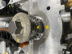
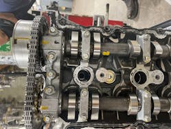
I was guided over to the Suzuki engine and the head rebuilder showed me how the crankshaft was lined up properly by marking the crankshaft index marking with yellow paint and mating it with a yellow mark on the engine block (Figure 6). Then I was shown how both the camshafts were in alignment with both of their index marks (at the backsides of their gears with yellow marks) that lined up with the yellow marks on the front cam retainer (Figure 7).
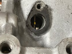
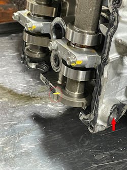
The timing chain seemed to be installed correctly but now I used my known-good trigger orientation patterns to prove out the trigger wheels. I had the rebuilder turn the crankshaft to place the sole “1” tooth crank trigger to line up in the crank sensor hole (Figure 8). Then I inspected the cam trigger to see where the first “1” trigger was, and it was off by at least 90 degrees of its shaft rotation (Figure 9, Yellow mark “1”). The trigger wheel was pressed on the camshaft with no indication of any problems but then when I looked at the crankshaft trigger wheel it was a trigger plate that bolted to the crankshaft. Was it possible that it was oriented in the wrong position?
‘Locating’ the culprit
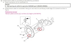
I searched in my information system to see if there was a procedure for removing and replacing the trigger wheel and I found it (Figure 10). This wheel was bolted on and located properly in place with a dowel pin so as not to put it in the wrong position. When we compared the picture with the engine, we discovered that the wheel was off one bolt hole. I stuck around while the rebuilder was gaining access to the plate and the owner came over as well.
It turns out that during the rebuilding process the dowl pin was removed when the crankshaft was reconditioned and never put back in place so one of the rebuilders simply placed the trigger wheel back on the crankshaft without giving any attention to how it was to be exactly lined up. Many hands go into rebuilding engines in a large facility like this and you cannot blame any one person. Things do happen in our industry, so we just resolve them and move on. I was so happy to finally find the underlying cause of the issue and form a new relationship with the engine facility; and at the same time ease the mind of the mechanics at the repair shop to end their dilemma.
The engine shop put the whole engine back together and delivered it to the repair shop where it was again installed back into the vehicle where it ran like a charm. I am sure that the engine rebuilder worked out a time loss refund with the shop and did the right thing. I felt sorry for both parties involved because our business is tough enough as it is, but I can only tell you that the resources we have available today make it a lot easier for us to resolve a problem, even if it means stretching across the globe on a waveform Journey for that missing piece of the puzzle. Sometimes, that is what it takes to resolve an issue in a repair bay. I am hoping that this story has touched many mechanics and technicians who have been down this similar road. It is all about the learning experience.
