Content brought to you by Motor Age. To subscribe, click here.
Welcome back to another edition of “The data doesn’t lie,” a regular feature in which I pose a puzzling case study, followed by the answers to the previous issue’s puzzle.
What You Will Learn:
• Computerized fuel injection systems strategize to maximize CAT efficiency/longevity, which isn't always at stoichiometry
• Correcting for a lean condition may mean closing the throttle instead of increasing injector pulse-width.
• Scan data provides information to determine if the cause of the symptom will be found with breathability, fueling, correction, default strategies
Although today’s computerized fuel injection strategies still shoot for the same goals as the ones from years past, how they go about reaching that goal and maintaining fuel control (especially in response to faults) is far different. If you aren’t aware, I suggest you pay attention.
When coupled with other newer technologies (like turbo/supercharging, Atkinson cycling, VVT/VVL, DoD) the benefits of the GDI fuel injection system are tremendous. The ability to extract the energy output of a big 8-cylinder can now be accomplished with a small 6-cylinder, and similarly from a 6-cylinder to a 4-cylinder engine. Moreover, they are far more fuel-efficient and emit far fewer contaminants from the exhaust stream.
But that technology comes at a cost to technicians faced with driveability issues. The components used to monitor and control these systems are more complicated and require a slightly more involved analytical skillset.
My good friend Caleb Mohler of European Service Center in Houston, Texas, was faced with a 2014 BMW X6, with a DOHC V8. This vehicle is turbocharged and includes two independent GDI fuel injection systems (two MAF sensors, two camshaft-driven high-pressure fuel pumps, and two separate fuel rails.) The vehicle presented with a P0303-Cylinder #3 misfire and would set the DTC only above 4,000 rpm.
Initial approach
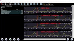
Using a Snap-on scan tool and the Snap-on upload website ShopStream Connect, Caleb gathered some basic graphical driveability data at the time of the fault, which he collected for analysis (Figure 1). What can be seen is the primary WRAF sensor is reporting Lambda 1.36. The secondary (post-CAT) HO2 sensor signal is not included in this capture but is reporting below .074mv. (Lambda 1.36 = 36 percent-lean-of -stoichiometry). Both sensors tell the same story, and the engine is operating in a very lean state. Although a DTC for a cylinder-specific misfire has flagged, we have to consider a globally lean condition to be the root-cause.
The next step is to determine why the engine is under-fueled. Reviewing a different data set shows that the MAF sensors (responsible for reporting engine load to the PCM for calculation of proper fuel delivery) indicate an inability for the engine to pump air adequately. It should be clear that if the PCM sees a lack of incoming air, it would deliver less fuel (because the fuel isn’t required). That begs the question “Why is the engine failing to breathe correctly?”
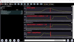
Reviewing yet another set of data PIDs reveals that answer quite clearly (Figure 2). Paying mind to the engine rpm value, it continues to climb (indicating acceleration). However, the throttle position sensors show that the throttle is being commanded to close, even though the accelerator pedal is being depressed (not displayed in the capture).
A diagnostics path was chosen
Considering what was stated in the beginning (how GDI platforms respond differently to faults), we can see in the data above that the PCM responded to the lean condition by closing the throttle. This means the apparent breathability fault was simply an effect of the throttle blade being commanded closed. So, the next question to be answered is “Why is the PCM delivering such a lean fuel charge?”
Caleb viewed a third set of data parameters (Figure 3). These were based less on “breathability” and more on “fueling.” The PIDs show that under heavy acceleration, the fuel rail pressure began to drop. Although only one of the FRP PIDs is displayed in the capture, this occurred on both independent fuel rails/both banks of the engine.
For clarity, I’ve compared fuel rail pressure to rpm and load (Figure 4). My goal in this data set is to see if the load dropped before the fuel pressure (cause or effect). It’s clear that the rail pressure dropped first, meaning this fuel rail pressure drop did not occur in response to a change in measured absolute load.
The data doesn’t lie
With all the information in front of us, we were faced with deciding how to proceed. Here are some bullet points of what we know to be factual, and I will ask all of you, diligent readers, for your input:
- P0303 is occurring, and it’s always under heavy/sustained load
- All four primary/secondary exhaust gas oxygen sensor report lean conditions for both banks during fault
- Both fuel rail pressure sensors report a loss over time leading up to the fault
- The apparent breathability issue is simply an effect of the adaptation to correct for a lean condition
Given this information, what would you recommend doing next?
- Gather more information about the commanded rail pressure and low-pressure fuel delivery system
- Replace in-tank low-pressure fuel supply pump
- Replace GDI fuel injectors
- Replace both high-pressure fuel pumps
SOLVED: (May 2023, Motor Age) 2014 Ram ProMaster 3.6L, overheating
What would you recommend doing next, given the data bullet points in last month’s challenge?
- Replace head gasket for suspect bank
- Defer to a different test due to inaccurate results from this test
- Repeat the test and place the pressure pulse sensor in the exhaust system and/or dipstick
- Replace head gasket and recondition cylinder head due to intake poorly-seating intake valve
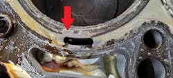
For those of you who chose answer #3, congratulations! This is likely the most logical approach. Although I always suggest deferring to tried-and-true tactics when current test results do not instill confidence, answer #2 would be acceptable as well. However, if you chose answer #1, replacing only the head gasket will correct the overheating /coolant loss concern but doesn’t answer the question about to where most of the compression was lost (Figure 5). Answer #4 is incorrect, as the cranking-intake pulse captured didn’t prove where the compression loss occurred but did prove the leak was not to the intake manifold (past a poorly seated intake valve).
By placing the pressure pulse sensor in the tailpipe, the compression loss fault would have been confirmed to be a poorly seated exhaust valve. After the removal of the cylinder head, the exhaust valve seat for cylinder #2 was displaced and the cylinder head required reconditioning. Even if this pressure pulse information is a current challenge for you to understand, capture it anyway. After the fault is confirmed visually, you can begin to put the puzzle pieces together and learn from them. Learn the techniques properly and practice!
Be sure to read next month's Motor Age issue for the answer to this month’s challenge and what was discovered!


