Diagnosing misfires: How to handle issues with fuel-related misfires
Editor's Note: This article was orginally published Dec. 15, 2015. Some of the information may no longer be relevant, so please use it at your discretion.
In our previous misfire articles in this three-part series, we discussed using and maximizing the data from your scan tool in order to determine various causes of misfires. This month, we will concentrate on fuel-related misfires and ways to find the root cause. There are some things you must keep in mind when diagnosing misfires, especially fuel-related issues:
- Fuel-related misfires can be caused by too much fuel.
- Fuel-related misfires can be caused by too little fuel.
- Fuel-related misfires can be caused by incorrect atomization of the fuel by the injector.
- Fuel-related misfires can be caused by bad fuel.
- In some cases the customer will not bring the vehicle in with an initial problem, but when additional issues occur.
These items are necessary to keep in mind throughout your diagnostic routine, but it is to your benefit to consider them early in your procedure. For example, if your scan readings show the system is lean, the cause could be a fuel delivery issue or caused by a high concentration of alcohol on a vehicle that is not built to a flex-fuel specification. Understanding the possible causes early assists in performing a complete diagnosis by not overlooking some potential sources of a problem.
Step 1: Interview the customer
This step may not seem necessary or be possible in some cases, but its importance cannot be overlooked. Customers may not notice, or be concerned with, issues that arise over a period of time such as a slight drop in power, but they will notice when a "check engine" light comes on. Because of this it is possible to have multiple problems with opposing symptoms on a vehicle that comes in.
For example, if your customer has had a drop in fuel economy (a rich condition) for a period of time they did not notice or were not concerned with, but brought the vehicle in with a "check engine" light and a lean code, you need to diagnose both a lean and rich condition without knowing there had been an issue causing the system to be rich. Asking questions of the customer such as their driving habits, if they run their fuel tank near empty, and if they have noticed any other issues will help you perform a complete diagnosis. The interview of our customer indicated no additional concerns or added any valuable information.
Step 2: Obtain fault codes and freeze frame data
Using your scan tool, first check all modules for communication looking for “U’ codes, meaning issues within the CAN system, and address those first. Next, you need to check for codes and obtain freeze frame data for all codes possible. Remember, some older scan tools only record freeze frame data for the first code while newer tools allow you to see the information on multiple codes.
If codes were present, the freeze frame data will allow you to see what the PCM was seeing from various sensors on the vehicle. Make sure you print this information because you can use it to operate the vehicle in those exact conditions to either duplicate the issue during the diagnostic process or to confirm the repair was successful. The only fault code on this Expedition was a P1000, which on a Ford indicates that the monitor tests are incomplete, most likely due to someone clearing codes.
Another indication codes have been cleared is when there is a current misfire and no code is present. Since the code(s) have been cleared there will be no freeze frame data. Not having all the codes and freeze frame information may make our diagnostic process slightly more challenging, but not impossible.
Step 3: Observe data stream
Observing the data stream from your scan tool is the next step, primarily the oxygen sensor and fuel trim data. One potential pitfall of fuel trim data is that fuel trim is based on oxygen sensor data and if a sensor is faulty, the fuel trim information data can be false.
The data from the Expedition showed the battery voltage was good, which is critical for both the fuel pump and injectors to operate correctly. The engine temperature, mass air flow (MAF) and engine vacuum were all within normal operating ranges. The oxygen sensor data showed readings within normal ranges in both voltage and time. Be aware that scan data is not the same as you would see with a lab scope. If oxygen sensor readings on the scan tool are either a little slow, or the voltage range is not within 15 percent of either the high or low limits, it is a good idea to check the sensors with a lab scope.
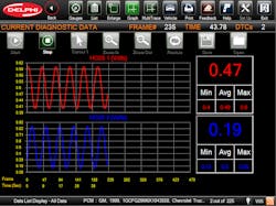
The fuel trims on the Expedition indicated no issues with either long- or short-term on Bank 2. The short term trim on Bank 1 showed it was subtracting fuel at 5.5 percent, meaning the injectors were on for 5.5 percent less time. Normally -5.5 percent Short Term Fuel Trim is not an issue, but combined with the long-term addition of fuel will be something to keep in mind during the diagnosis.
Mode $06 data indicated multiple misfires on Cylinder 2.
Step 4: Obtain vehicle specs and complete diagnostic worksheet
Obtain the vehicle specifications for fuel pressure and other items pertinent to engine operation and proper fueling such as MAF value and engine temperature to complete a diagnostic worksheet. We tested the fuel pressure and found an abnormal reading. The specification is 35-45 psi. The regulated (with vacuum attached) reading at idle is 33 psi, which is slightly under the specification (see The reading unregulated was 35 psi, which is quite a bit less than what is specified and would be required to operate properly at higher rpm.
Taken by itself, the fuel pressure being low will not typically cause a single cylinder misfire, but it is an indication of multiple problems. Based on the Mode $06 data of a misfire on Cylinder 2, we installed a lab scope on the injector connector. The waveform showed normal and also indicated the added injector "on time" as indicated by the fuel trim numbers. If the injector had been faulty due to high resistance, the waveform voltage spike would have been lower as shown .
We then used a digital multimeter (DMM) to check for resistance in the injector. The resistance measured 14 Ohms, which is well within spec of 11-18 Ohms. Resistance testing with a DMM may be useful if the faulty injector is way out of specification. Remember that it is a comparative test to the other injectors on the same vehicle under the same conditions (engine temp, fuel quality, etc.) and small variances may affect injector function slightly, but will probably not cause a misfire.
We still believed we had a fuel-related misfire due to the fuel trim on Bank 1 so we wanted to check the fuel injector itself. One way to determine if an injector is delivering fuel at the same rate of other injectors is to use an injector pulse tester and fuel pressure gauge. Begin with relieving fuel pressure in the system per the vehicle manufacturer’s procedure. Next, install the fuel pressure tester according to the tester’s instructions. Disconnect the fuel injector connector and install the fuel injector pulse tester on the injector. Pressurize the fuel rail by turning the key “on” for about 10 seconds, then turn the key “off." Note the fuel pressure.
Next, you will energize the pulse tester which triggers the fuel injector a calculated number of pulses. This will drop the fuel pressure due to fuel flowing through the injector. Note the fuel pressure again.
Perform the same test with multiple cylinders cycling the key "on" and "off" each time to pressurize the fuel rail between tests. The fuel pressure drop should be the same for each injector. Lower amounts of pressure drops indicate an issue with an injector not flowing the same amount of fuel. Our test showed a pressure drop of 4 psi on Cylinder 2, and 8 psi on the other cylinders tested, indicating that Cylinder 2 was not flowing as much fuel.
Step 5: The repair
We have determined we have a faulty injector on Cylinder 2. At this time there are a few things to consider, one being can or should you recommend replacing all of the injectors?
First, you can make a good case for replacing all of the injectors. They are all the same age and have the same number of miles on them as well as having had the same fuel quality going through them. In a perfect world, replacing them all would most likely benefit the customer, both in fuel economy and performing a complete repair with less likelihood of a future failure. It is not always a perfect world due to cost considerations with many customers and it may be necessary to replace just the faulty injector in some situations. In the case of our Expedition, the customer says they will be replacing the vehicle soon and did not want to replace all of the injectors.
It is now time to take a few steps back and review our fuel trims and fuel pressure. Fuel trims that indicate rich short-term and lean long-term conditions in many instances are caused by a fuel pressure regulator that is leaking. When the diaphragm within the regulator is faulty it allows fuel to be drawn into the vacuum hose at idle causing unmetered fuel to enter the intake manifold. The faulty regulator also prevents the system pressure to increase under load, causing a lean overall condition at higher RPM. The lower-than-expected fuel pressures observed during our testing procedures also can be attributed to a faulty pressure regulator.
Having multiple issues on this vehicle created a situation where it was necessary to look beyond just one or two of the symptoms. The misfire caused by a faulty injector should have created positive fuel trims, adding fuel and oxygen sensor readings showing lean. Because there was also an issue with a fuel pressure regulator leaking fuel into the intake manifold, it created a situation where just observing scan data would not take you directly to the cause of the misfire. After replacing the faulty injector and pressure regulator the misfire was repaired and the fuel pressure and fuel trims returned to normal values.


