Getting the most out of your digital storage oscilloscope
Content brought to you by Motor Age. To subscribe, click here.
What You Will Learn:
• All tools have limitations
• DSO will let you see systems function dynamically
• Faults can easily be detected, even when symptoms aren't currently present
Efficient and accurate diagnostics calls for a recipe — one that is derived from knowledge of how a system's components function (at the most basic level), an accurate description of how these components make up the system and last, but certainly not least, an accurate way of evaluating the performance of these components with certainty. The digital storage oscilloscope (or DSO) is the measuring device that can do that for us, in almost any automotive situation you can imagine.
Everything has a limit
I’ve heard it a million times: “I don't need a scope; I do just fine with my digital multimeter (DMM).” As true as that may be in many situations, each and every tool available to us as technicians has limitations. It’s absolutely crucial that we take the responsibility of learning the limitation of the tool we choose to implement, along with the limitation of the test we are about to perform.
For instance, consider the noid light, a trustworthy tool that many of us have relied upon for years to give us some basic preliminary information about the nature of a “Crank/No-start” scenario. We are aware the noid light is there to temporarily replace perhaps a fuel injector. When the engine is cranked over, the rhythmic flashing of the noid light signifies to us a boatload of information indeed. Consider what it's telling us:
- CKP input
- PCM alive, processing and generating an output (injector pulse)
- Circuit integrity from the battery, through the injector, and back to ground, via the PCM driver
This one test did provide a lot of data and very rapidly, with virtually no time invested. It gives us a great advantage as it tells us where not to spend any precious diagnostic-time. But again, we have to consider the limitation of the tool and the test. Questions like the following should arise each time you select a tool and a test:
- How much current does the noid light actually draw?
- Is it possible that the PCM driver can handle the noid light current, but not the injector’s?
- Is the noid light test truly stressing the circuit adequately?
Without asking those questions and considering the limitations we may find ourselves “verifying” the operation of a circuit when in fact, it may be faulted and we inadvertently stepped right past the actual problem.
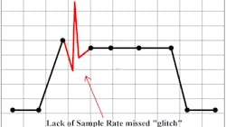
Now, back to the DMM. That too has limitations. A DMM measures the differential in voltage between to the two test leads within the circuit being sampled. It does this many times in a second. What the DMM then does is average the individual samples together and display the result of that average on the meter screen. This leaves a lot to be desired. The lack of sample speed from a DMM can easily fail to capture potential faults, represented here (Figure 1). Without this understanding of the DMM's operation, one could easily draw false conclusions.
A picture is worth 1,000 words
A DSO happens to work very similarly to a DMM, only it samples a much higher rate, giving the DSO a more accurate representation of what it is actually measuring. This is known as the sample rate. One of the most widely used DSOs can sample at 400 million samples every second (at its fastest capability). But probably the best aspect of a DSO is its graphical representation of what it is measuring. It plots these individual samples as dots, over a period of time. Each of these dots (or sample points) is connected from left to right with a line. This gives us a picture of the voltage changes. Being able to monitor the changes in voltages over time means we don’t have to stare at the DSO’s display, waiting for the next numerical change to occur. We can simply glance back in the history of the recording.
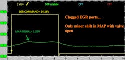
Furthermore, a DMM can only sample and display one circuit’s measurements at a time. The DSO allows us to sample from multiple circuits simultaneously, enabling us to view from an action/reaction perspective. Yes, we can see the result of a system’s components operate and carry out their function (or fail to do so) quite easily. Here is an example of an EGR system failing to reintroduce inert exhaust gas back into the intake manifold (Figure 2). It can be seen, the pressure in the intake manifold (represented by MAP signal) fails to rise as the EGR valve is energized. You had better believe that when I cleaned the EGR passages of carbon, a repeat of this test showed the MAP signal going sky high, just as it should!
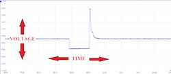
A DSO is designed to display changes in voltage vertically and the passing of time horizontally (Figure 3). But the versatility of the tool allows us to evaluate a circuit functionality from many other aspects as well. The scope allows us to monitor the characteristics of a signal, rather than just the signal itself. Allowing us to make certain aspects of the incoming signal easier to see. Allow me to demonstrate.
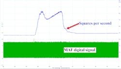
A two-trace capture of the same MAF digital signal is displayed (Figure 4). The GREEN trace is showing the actual digital signal, as sampled directly from the output of the MAF sensor; It’s a square wave. The frequency of the signal (or how often the square waves occur) is what the PCM is concerned with. An increase in frequency is equivalent to an increase in airflow. Although it appears that the GREEN trace is a thick, solid line, it is actually a very rapidly cycling square wave. It transitions from zero volts to five volts, and back again over 13,000 times every second!
Clearly, this is very difficult to see with our eyes and would certainly be almost undetectable if there was a momentary drop-out in the MAF signal. Now, focus your eyes on the BLUE trace. This is the same signal being sampled but the scope has been commanded to display hertz (Hz=cycles per second). This is allowing the DSO to do the evaluating and it will displace a change in Hz when there is a change in airflow and clearly indicate a drop-out in MAF signal in the case of a deficiency. This is far easier to evaluate for a deficiency and would be virtually impossible without the use of the graphing capabilities of a DSO.
Strategize to accessorize
For the same reason DSOs display changes in voltage over a period of time, the available accessories (like current probes and pressure transducers) will output a voltage that equates to a physical quantity, like pressure or current flow. Utilizing devices like these is icing on the cake and will allow you to take your diagnostics to the next level and multiply the power and return-on-investment of your DSO.
In an example coming up, you will see shortly, a comparison of a healthy A/C compressor clutch/pulley to that of a faulted one. The backstory behind this is due to a customer arriving at the shop with the complaint that the A/C functions erratically. It blows ice-cold when it functions but only ambient temperature when it is acting up. Sometimes, it just takes a very long time to get cold. A visual inspection revealed that during the exhibited symptom, the A/C compressor clutch failed to engage. Scan tool data confirmed the request for compressor operation was present, the fuse was intact, and the compressor clutch relay was audibly functioning.
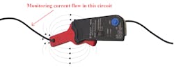
The next step was a quick test for current flow through the A/C compressor clutch circuit. This was carried out in only 30 seconds, and right at the fuse box. Because a current probe was used, there was no need to open the circuit up (Figure 5). The comparative results displayed some very interesting and helpful facts. Both the healthy and faulted amperage waveforms show almost identical current-flow amplitude (Figure 6). Understanding Ohm's Law allows me to conclude that if the current is the same in both the healthy and faulted circuits, the symptom has nothing to do with the following:
- A lack of voltage supply to the A/C clutch coil
- Insufficient ground supply to the A/C clutch coil
- A resistance issue within the clutch coil itself
It's not possible to have good current flow if there is added resistance or voltage-drop anywhere else in the circuit. If this was the case, the current flow would indicate this as a lower-rising current ramp. So, this test just proved there was nothing wrong with the circuit electrically.
There is another equally important characteristic of this waveform. Referencing the healthy current ramp, you can see a deviation (or pintle bump) in the current trace, about 60 percent up the rise of the ramp. This represents physical movement. As a ferrous metal is moved within the coil windings of an inductor (like an A/C clutch coil) it impedes current flow. This deviation is an indication that the clutch actually engages. If you then reference the faulted current ramp, it can be seen that the bump is present, but there is a large delay in engagement, from the time the magnetic clutch was energized.
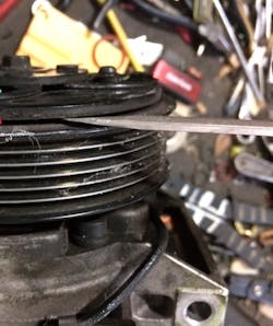
This information from a single test gave me a sense of direction. It gave me the sense to inspect the air gap of the A/C compressor clutch. The specification calls for an air gap no larger than .024”. The measurement proved to be far larger than that (Figure 7). In under 10 minutes, the mysterious problem was solved, and the vehicle was fitted with a new A/C compressor clutch. The combination of the DSO and a powerful accessory like the current probe, allowed me to watch the actual work being performed dynamically in the circuit, not just the command to energize the compressor clutch coil.
Let the DSO tell the entire story
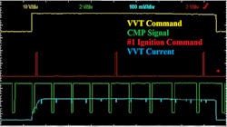
As mentioned earlier action/reaction testing is one that definitely allows you to grow as a technician. Not only will it help you fix cars but also to gain a better understanding of the functionality of the components and the systems they make up. This scope capture of a typical VVT system (variable valve timing) carrying out its duties. The four individual scope traces represent the following:
- YELLOW = Voltage command to the VVT solenoid (to signal the energizing of the VVT solenoid)
- GREEN = Camshaft position sensor signal (to display a change in camshaft position)
- BLUE = Current flow through the VVT solenoid (to show the “work” performed)
- RED = Command to #1 ignition coil (Just a simple trigger, no significance to the analysis)
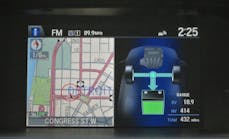
As voltage is driven into the solenoid circuit, it can be seen that the current begins to rise. About 60 percent up the current ramp, a pintle bump is visible. This indicates the VVT solenoid spool valve is physically shuttled. Just milliseconds later, the camshaft position sensor signal began to display a shift in the camshaft phase (as can be seen by the change in square-wave frequency. This was accompanied by an audible change in engine idle quality (Figure 8).
The scenario played out above is in a known good functioning vehicle. It clearly displays the entire chain of events that must occur to generate a shift in the camshaft phase. Imagine this in a scenario where no shift in the camshaft phase occurred. Imagine a normal rise in the current ramp but lack in pintle-bump being displayed. What would you do? Logic would tell you that with the normal current flow but no visible pintle bump, it's likely the spool valve within the solenoid is physically stuck. This observation necessitates removal and visual inspection of the VVT solenoid itself.
Conceive, believe and achieve
It's not magic, it’s just physics. Knowledge of how components function, at their most basic level, is typically all it takes on your end. The good news is that everything you are about to read below exists on almost ALL VEHICLES! These are the things I urge you to master and make second nature. Understand first, that “inputs” most often display a representation of: ·
- Position
- Angle
- Pressure
- Temperature
- Speed
They will either be a variable-reluctance sensor, a hall-effect sensor or a magneto-resistive element sensor. These typically are used for speed or position. Thermistors are used for temperature and potentiometers to show a variation in angle. Again, these function the same, regardless of the vehicle you are faced with.
- “Outputs” are typically inductive devices like:
- Solenoids
- Relays
- DC motors
- Step-up transformers (ignition coils)
Just like the inputs, the outputs, too, are virtually the same devices on every vehicle you are faced with. Really invest the time to do some training to learn how these components function. It will be time well-spent as it will serve you throughout the workshop every day! My challenge to all of you who have not yet invested in a DSO…get one! and practice with it, on known good vehicles. Save your captures and learn from them.
In no time at all, you will find yourself being the true problem solver of the shop. You will find yourself working more efficiently, making fewer mistakes and the workday will become a fun challenge for you. Are you up to the challenge?
