Solve driveability issues, emissions-related failures with fuel trim diagnostics
What you'll learn:
• Air-fuel ratio vs. equivalence ratio and why you need to consider both when addressing fuel trim related challenges
• How to obtain cylinder air flow measurements for quick and dirty V.E. testing
• Develop a deeper understanding as to how the ECM determines the proper amount of fuel to be delivered to the cylinder at all times.
Fuel trim is a vital data point technicians can leverage when assessing vehicle anomalies related to driveability and emissions challenges. Additive, block learn, integrator, multiplicative. You may have seen any of these terms in the past and essentially, they're all indicative of the same common term, fuel trim. Fuel trim is the correction factor applied to the air-fuel mass delivered to the cylinder during engine operation. Small errors in this cylinder air/fuel mass estimations are expected but larger errors are an indication of trouble. Further, it typically takes a significant error to result in an illuminated malfunction indicator light accompanied by diagnostic trouble codes (DTCs). The source of these errors is not always easily identified and therefore the goal of this article is to provide a deeper understanding of how errors can occur and what tools and techniques a technician can apply to form a hypothesis to recommend a service/repair operation.
Engine basics
The four-cycle internal combustion engine (ICE) has evolved tremendously over the years. The advancements have been primarily driven by the desire to squeeze more energy from the ICE while using less fuel and producing fewer tailpipe emissions. What we’ve witnessed over the past decade or so with engine design and strategies is amazing. With the implementation of variable valve timing, engineering teams in some cases were able to eliminate the use of an external EGR valve and were able to expand the torque output of the engine across a wider engine speed range. However, the engine controller needs to have a clear understanding of the actual mass of air always entering the cylinder to deliver the right amount of fuel to match the desired air to fuel ratio. The way this is measured and interpreted has changed dramatically over the years and we’ll discuss this further within this article.
Sensors mounted in the exhaust upstream from the catalytic converter are the primary feedback indicators used to report back to the ECM how well the fuel delivered to the cylinders. matched the estimated cylinder air charge to achieve the targeted air-fuel ratio. A wide-band oxygen sensor (Universal Exhaust Gas Oxygen – UEGO) is more expensive and complex, but the benefits it provides is crucial in obtaining accurate air-fuel ratio measurements across a wide range of mixtures. However, the narrow band sensor is only accurate to mixtures very close to stoichiometric.
In years past, vehicles used narrow band sensors to achieve a tight average of stoichiometric air to fuel ratio to the combustion chamber by constantly switching the air to fuel mixture rich-lean-rich-lean repeatedly. The wide-band sensor being used today is far superior and allows calibration engineering teams to squeeze more efficiency out of today’s internal combustion engines and provide the optimal catalytic convertor feed gas to achieve the lowest possible tailpipe emission output. Additionally, these sensors are typically ready for work shortly after engine startup. Narrow-band sensors can still be found downstream of the catalytic converter and are primarily used for monitoring catalyst efficiency. However, some vehicles use this sensor to “fine tune” the catalyst’s feed gas by trimming fuel in a way so that the catalyst can do everything it can to further reduce tailpipe emissions.
Air-fuel ratio
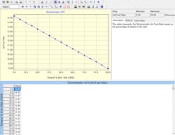
Today’s pump gas typically contains up to 10 percent alcohol which means that the proper air-fuel ratio is now less than the customary 14.7:1 ratio we experienced in the past. Some vehicles are designed to operate on varying percentages of alcohol therefore the ECM needs to have a clear understanding of this content so that the proper stoichiometric air-fuel ratio can be targeted (see Figure 1). Some vehicles use direct measurements to detect alcohol content and others use inferencing to estimate alcohol content. Today, with most pump gas containing approximately 10 percent alcohol, the stoichiometric air fuel ratio target is in the lower 14’s. In most cases the scan tool offers air-fuel ratio PIDs in different formats such as equivalence ratio, lambda, phi, and air-fuel ratio. Later in this article you will see why one would want to choose one over another or observe both.
Figure 1 – Ethanol percentage stoichiometric air-fuel ratio table
This method is still in use today however some of the behind-the-scenes routines may have changes. Essentially, a speed density system uses a 3-D table to express the volumetric efficiency profile of the engine across a wide range. The system typically uses engine speed on one axis and manifold pressure on the other. This table is generated during engine development and then written to the engine calibration residing within the engine control module. This “map” is used as a baseline reference to understand what the percentage of cylinder fill is when operating within specific coordinates. For example, using Figure 2, say the engine was operating at 1600 rpm and the manifold pressure was 50 kPa. The reference table states that the cylinder fill capabilities are 75.09 which means that the engine can fill the cylinder 75.09 percent of the actual volume of the cylinder. So, on an engine with a 4,278cc engine, the cylinder volume is 713cc. Essentially, this means that air mass entering the cylinder is would only fill it to 75.08 percent of the 100 percent rated size of the cylinder. Since the engine controller knows the cylinder size, the injector flow rate, the composition of the fuel, density of the air, and the desired air-fuel ratio, it will then know how long to turn on the fuel injector. It will then look to the result of the air-fuel ratio indicated in the exhaust to see how that math worked out. Any errors in hitting that target will result in a correction issued via fuel trim. For the driveability technician, the manifold pressure sensor key on, engine off (KOEO) reading should always be referenced when performing analysis on any driveability or emissions related complaint. If this value isn’t properly reporting your station pressure, then the powertrain control module (PCM) will not be referencing the proper coordinates within that table during engine operation.
Figure 2 – Speed density table
Mass air flow systems
Many engines use mass air flow sensors to estimate/measure cylinder air flow. Most engines utilize a single sensor while some use multiple. The ECM uses the input from the mass air flow sensor to calculate the cylinder air flow. The output from the mass air flow sensor can be used in conjunction with other data parameters by technicians to assess various conditions. For example, if the technician suspected that the engine wasn’t flowing the amount of air it should, either because they suspected a restricted exhaust or an under reporting sensor, they could use this as an input. However, what I have found is that where this value is sampled is not always the best. Recently I was hosting a training session and polled the class for where one would typically want to sample the mass air flow reading when performing a volumetric efficiency test. The majority of the attendees stated that while at wide open throttle (WOT), the rpm just before the shift point should be where the mass air flow value should be sampled. Well, this answer is correct only if that rpm is where the engine under test is rated to produce its maximum torque rating. But in most cases, this is not where the engine produces its maximum rated torque. So as a best practice, one should try and sample the mass air flow reading at the rpm where the engine is rated to produce maximum torque. From there, one can take that value into a volumetric efficiency (VE) calculator for calculation. Or one could use some quick napkin math to roughly figure the efficiency of the engine. To do so, one needs to calculate using the following equations.
To find cylinder air we need the following:
-
Engine speed in rpm
-
Mass air flow (MAF) in grams/sec
-
Constant (based upon the number of cylinders)
The equation is as follows: (MAF x constant)/rpm
To find the constant we use the following formula (120/cylinder count) or use the following table:
| Cyl | Constant |
| 4 | 30 |
| 5 | 24 |
| 6 | 20 |
| 8 | 15 |
| 10 | 12 |
| 12 | 10 |
Then one would need to know what the theoretical 100 percent-cylinder air mass would be. Say that we had a 2.7L 5-cylinder diesel, you would take 2700cc and divide that by 5 to get 540cc or .540L. Next, we need to know the mass of air that would fill that area. To find this we’ll reference a known value and that is 1.184 grams of air at standard temperature and pressure will fill 1L. So, if we take 1.184 X 0.540 = 0.639. This means that if we perform our measurement from mass air flow and arrive at .639 grams/Cyl we would be at 100 percent volumetric efficiency.
Mass air flow and speed density methods have been the traditional pathway for predicting cylinder air during engine operation for most manufacturers. However, there are some today using other methods such as neural networks to build artificial intelligence with great success.
Fuel trim diagnostics
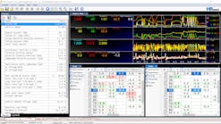
Fuel trim is a key indicator of how well the overall engine performance and fuel delivery systems are performing. For service technicians, it can provide an invaluable path towards a resolution. As mentioned earlier, it usually takes a wild swing in fuel trim to flag a fault and therefore fuel trim can be used to identify trouble before it flips on the malfunction indicator lamp (MIL). It’s always a good practice to monitor fuel trim along with a few other parameters when assessing engine performance issues. Knowing what can drive fuel trim numbers can help technicians arrive at the right hypothesis and therefore issue the proper repairs that generate success. Looking at Figure 3 you can see in the lower graph that >20 percent fuel is being removed via long-term fuel trim (LTFT) on both banks. Based on the data, what do you see?
Figure 3 – Fuel trim anomaly due to incorrect fuel composition
This vehicle is a flex fuel vehicle and the revealing factor here is that while the engine control module (ECM) was targeting EQ or Lambda 1, the commanded air-to-fuel ratio at 11.63:1. This means that the ECM had inferred the composition of the fuel to have roughly 52 percent ethanol. The other anomaly here is that the mass air flow signal is over reporting air flow. Figure 4 shows the engine data following the replacement of the mass air flow sensor (MAF) and a reset of the fuel composition using the scan tool.
Figure 4 – Fuel trim correction after service
Monitoring and recording engine performance parameters can produce great reference material for diagnosticians. Having a deeper understanding of the inner workings of the ECM and its various strategies will no-doubt bear success when dealing with engine performance and emissions related challenges.


