Content brought to you by Motor Age. To subscribe, click here.
What You WIll Learn:
• Always acknowledge each DTC preliminarily as they may be a valuable clue
• Do not approach network communication faults without a topology diagram and wiring diagram in hand
• Use data driven analyses to triangulate the location of the fault
"Hey, Nice Try"… “You’ll figure it out eventually"… “Third time is the charm"…These are phrases I’m sure we all dread hearing but likely all of us have heard them at one time or another. Well, there is no story I’d love to share more with all of you than one where I’ve had my rear-end handed to me. Let’s capitalize on my mistakes and so we can all take something away from them. After all, "failure" only exists if you don’t learn from your mistakes. I will NEVER forget this vehicle or the chain of events that consumed 18 hours of my life.
The challenge
I was called into a local transmission shop to analyze a 2015 Chevy Tahoe 5.3L (Figure 1). I was told by the service advisor that upon reception, the 6L80 transmission was in shambles and needed to be completely rebuilt. Although the procedure was carried out flawlessly, a fault still existed that didn’t sit well with the highly recognized shop. It seemed the shift indicator would intermittently not report the range the transmission was in at that time. On the display, it would flash whatever position the shifter was in when the fault occurred, and it would not change.
After further discussion, there were no driveability faults discovered, although there was a series of communication codes present in multiple nodes. I was told another mobile diagnostician had attempted a diagnosis and concluded that the transmission electronic-hydraulic control module (TEHCM) needed to be replaced. His advice was heeded, and the component was replaced and programmed. However, the fault remained. This is what I was handed.
I began my approach with a global scan. It’s common knowledge that with today’s virtual system platforms, information is shared over multiple communication networks, and sometimes, many ECUs. And any one of them could hold clues to help triangulate where the fault may lie. After obtaining 32 DTCs in 16 different ECUs, they were documented and all DTCs were cleared to see what faults were related to the symptom and which ones may not be related to the present fault. Getting rid of some of this “distraction” can certainly help focus one’s efforts.
After clearing the DTCs, the key was placed in the “RUN” position and the fault wasn’t present. The shift indicator in the instrument panel cluster would report properly for all ranges. However, when the engine was started and the shifter was moved, the fault occurred, always about two seconds after the engine was started. By this time, the shifter was in the REVERSE range. Although I continued shifting through the other ranges, the “R” on the cluster continued to flash. I repeated the global scan, and many communication-related DTCs remained in all nodes, as well as some minor “unrelated” circuit DTCs.
The initial approach
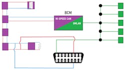
Step #1 is to establish how the shifter position information from the transmission makes its way to the cluster. To determine this requires visiting service information for both “description and operation,” as well as the wiring diagrams of the communication networks. The TEHCM is mounted internally to the transmission and communicates on the high-speed CAN bus. It houses a mode switch that reports shift position to the self-contained ECU. This information is then shared with the body control module (BCM) also on the high-speed CAN bus. The BCM also serves as a gateway, meaning it speaks multiple languages. One is “high-speed CAN bus” and the other is ”GMLAN.” GMLAN is a slower network/language but is one that the instrument cluster speaks (Figure 2). It’s this language that allows the BCM to communicate the shifter position to the cluster. It was my challenge to determine why and where this information gets misconstrued.
Staying true to form, I always seek the information I can gather without too much time or energy invested. So, what can be extrapolated from the collected DTCs? Well, it seems that almost every node (ECU on the network) is none too pleased with the BCM. This is not only exhibited on the high-speed CAN bus but also the low-speed GMLAN network. Taking this a step further, I can communicate (using the scan tool) with every node on both networks (including the suspected BCM). What’s the significance? There is nothing wrong with the infrastructure:
- No open communication circuits
- No shorts to voltage/shorts to ground on the communication circuits
- No shorts exist between the two-wire twisted pair that the CAN bus data rides on
This information is important, because the more I discover upfront, the less pinpointed testing will have to be carried out later.
Triangulating the location of the fault
The logical approach would be to consider what was determined above to calculate my next move. Well, only a few possibilities exist now, as we get closer to the underlying cause of the fault. There is either a faulty BCM or an insufficient voltage/ground/or ignition feed to the BCM.
After careful thought, I may have made a dangerous assumption. But in fairness, I’d like you to hear the method to my madness. I decided to forego the testing for adequate voltage/ground/ignition feeds. I know, sounds crazy, but the fault only occurs initially, and then it clears up as the vehicle is run longer. In my experience, voltage drops worsen in time/with heat, not improve. Again, it could have been a “dangerous” assumption and not a recommended thought process, but it's the one I chose.
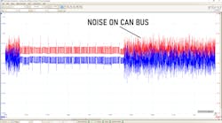
At the point I was ready to condemn the BCM, I decided to monitor the high-speed CAN communication network’s activity with the digital storage oscilloscope. It’s the only way to truly see the messages being shared and the integrity of that data. During KOEO or when the vehicle was first started, the activity looked very clean, as one would expect of a healthy network. But after two seconds, the fault appeared, along with some terrible “noise” on the network (Figure 3). I removed the serpentine belt to eliminate the alternator as the source of the noise, but the noise persisted.
So, is the noise the cause of the fault, or is it evidence that an internal BCM fault exists? To determine this, I would have to isolate the BCM from the rest of the network to see if the noise would disappear with the BCM eliminated.
I started the vehicle again while monitoring for noise at terminals #1, #6, and #14 of the DLC. These are the terminals for the communication networks. Once the noise was visible, I unplugged connector #1 of the BCM. This eliminated the noise, but this question remained:
Is the noise gone because the BCM is eliminated, or is it gone because everything “downstream” of the disconnection is eliminated?
To further pinpoint the possibilities, I employed a pair of jumper wires to bypass the BCM but keep the rest of the network intact. This effectively eliminated the BCM but also allowed me to see if another node downstream was responsible for the noise on the networks (Figure 4). In this fashion, the noise was eliminated. This process proved that the BCM was the source of the noise. I made my recommendations to the shop for BCM replacement.
A week later, they called to tell me the BCM was replaced but the same fault still existed. I was very surprised, but not more than I was embarrassed. Duty called, and a shot at redemption is what I was thankful for. I arrived at the shop to begin my approach again. Long story/short version… after a combined total of 18 invested hours (over my visits), I arrived at the same conclusion. I knew it was incorrect, so as I sat in the driver’s seat, I made an accidental discovery.
Pinpointing the root cause of the fault
As a courtesy, to eliminate shining the headlights on the other techs in the shop, I commanded the Auto Headlamps “off.” When I did that, I noticed that the gauges in the cluster seemed to dither a bit, and the cooling fan audibly slowed significantly. Still having my lab scope connected to the DLC, I noticed that the noise went away with the headlamps off.
At this point, I figured I would move the shifter and see how the indicator responded. To my delight, the indicator worked properly with the headlamps “off.” I could clear all DTCs, and they would stay away. When I commanded the headlamps “on” again, the noise returned on the data busses, along with the shift indicator malfunction and all of the communication DTCs.
Then, it hit me like a ton of bricks. On day#1 initial global DTC scan, there were a few headlamp control circuit faults (remember the “unrelated DTCs?”). I didn’t give it a second thought, as I wasn’t there to address anything but the shift indicator issue. After all, the headlamps worked perfectly, nice and bright.
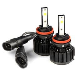
Upon visual inspection, I found that the original halogen bulbs were replaced with LEDs (Figure 5). Could this be the issue? I had to settle this once and for all. With permission, I replaced both headlamp LEDs with the correct halogen bulbs. To my delight, when the headlamps were commanded on, they functioned perfectly, the noise was no longer present on any of the networks, the DTCs vanished, and the shift indicator functioned normally.
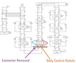
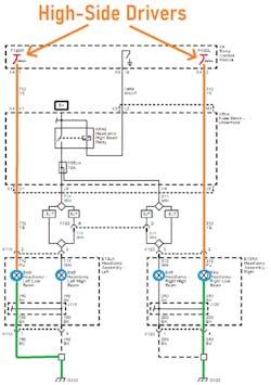
To understand how this chain of events occurred, I had to view the diagram (Figure 6). The BCM controls two independent high-side drivers to directly control the output to the headlamp bulbs. As the circuits are energized, they are monitored via voltage-drop in the BCM. If the BCM doesn’t like how the circuit is functioning (shorts/opens) it de-energizes the circuit and repeats the process (sets DTCs as well).
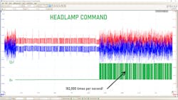
I continued to view the data busses with the lab scope but added a fourth channel. I decided to monitor the control circuit to one of the headlamps to determine how the noise got into the BCM. After all, these were LEDs (not High-intensity discharge lamps); they use very little energy and should not generate any EMI or RFI (electromagnetic interference or radio frequency interference).
Because I failed to save the capture, I recreated it here (Figure 7). The BCM continued to attempt energizing the circuit but would turn it off almost instantly when it didn’t see the correlating voltage drop it was programmed to desire. This process repeated itself until the DTC set and the BCM stopped trying (the reason the noise/symptom vanished over time). Zooming in, it can be seen that the BCM command to the bulbs cycled at a rate of 182kHz! This was the noise wreaking havoc on the BCM, and ultimately all the communication networks.
The takeaway? I will never again ignore DTCs pertaining to output circuits or fail to consider them as a source of noise, back-feeding into an ECU. This important clue was staring me right in the face and I never considered it. This fault should've been discovered early on in a preliminary inspection phase of this analysis. I'm a better tech because of it, and I'm grateful. This is why I’m sharing my pitfall with all of you. Don’t make the same mistake I did.
Sometimes we walk away from a situation with egg on our face. It’s ok; it happens to all of us. We all make mistakes, and it’s never gratifying. But it’s what you do with that information that ultimately determines if you’re successful, even if it originates from what seems to be a failure.

