What you will learn:
ADAS components
ODD – OEDR (Operational Design Domain – Object & Event Detection and Response)
Diagnostics and Calibration
Business opportunities
Tying it all together
Driver assistance systems (DAS) have been a part of the automobile going back many years with the introduction of such systems as ABS (antilock braking system), TC (traction/stability control), TPMS (tire pressure monitoring system), etc. Looking back, these systems had an impact on service because of the required product knowledge and oftentimes the adoption of new tooling to competently service such vehicles. Today, the common acronym we see is ADAS, which added the term “advanced” based upon the new features that either augmented the current DAS, or introduced brand new vehicle capabilities.
Many of these systems support active safety and go a long way toward preventing collisions and/or reduce the injuries received from a vehicular accident. In this article, you’ll learn about these systems, service challenges, and opportunities.
Camera systems
Cameras found on today’s vehicles naturally provide visual support not only for the vehicle operator but may support operations such as lane keeping, collision avoidance, and more. When you start to think about how these cameras work within these systems, you need to drop the assumption the camera sees exactly what humans see. Machine vision science is extremely sophisticated, and there’s a lot more than just photon detection going on behind the scenes. For many vehicle systems, it is likely that the camera system is providing parallel layers of vision support simultaneously.
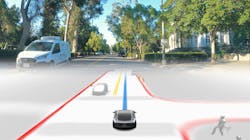
For example, a camera may be tasked with performing lane monitoring operations where a special filter is applied to the signal for processing lane markings and measurements as they relate to the vehicle they’re mounted on. At the same time, there may be another service running that performs object detection and classification, and there may be a pose-detection program running tasked with estimating/predicting human movement around the vehicle. Humans on foot and on bicycles are considered vulnerable road users (VRUs) and are a high priority within the onboard DAS (Figure 1).
Cameras mounted high and center behind the windshield are mostly used for lane keeping and object detection/classification. However, I recently had a 2014 Nissan Rogue in the shop with lane departure warning (LDW) without a windshield area mounted camera. Service information revealed this system will not work below 45 mph and is supported by the camera located at the rear of the vehicle. This is an SAE J3016 Level 0 vehicle, which means the system will only provide visible and/or audible warnings to the driver.
The rear camera is also used to support blind spot warning (BSW) as well. Since this is a critical input for the proper operation of both systems, the camera is supported by a washer and blower system aimed at keeping the camera lens clean. In the event of low washer fluid, both systems will be temporarily disabled until the fluid reservoir is refilled. When calibrating the rear facing camera, please refer to bulletin NTB14-072 titled: “2014 Rogue; Target board placement for rear camera calibration.” Under the notes section, you will find the following statement about operation:
“The Rear-View Camera monitors the traveling lane. It transmits the camera image signal to around view monitor control unit for the Lane Departure Warning (LDW) system.”
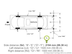
The bulletin states the distances listed in the service manual are incorrectly supported by the following graphic (Figure 2).
Radar systems
Radar sensors use electromagnetic radio waves to sense the distance to objects within its cone of rays by measuring the time of flight (ToF), and the incident angle between the transmitting (Tx) and receiving (Rx) antennas. Typically, the radar sensors used for adaptive cruise control (ACC) operate in the 77-81 GHz range. What this means is these radio chirps are being transmitted in the order of 77-81 billion times per second.
There are highly complex algorithms (usually taking place within the sensor) before its data is shared with other systems on the vehicle. The radar sensors used on the rear corners of the vehicle mostly operate at lower frequency ranges (24 GHz). Radar sensor that resides behind body panels are tunes specifically for that environment, so any changes to the body, repair, paint, etc. could negatively affect its operation. Consult service information for more information.
Additionally, these sensors are very delicate and most have a statement on the body stating they should be discarded if dropped. If you find yourself addressing one of these sensors that has been in a collision where the sensor and/or surrounding area suffered an impact equaling the shock from a drop, then a new sensor should be installed and properly initialized and calibrated.
Lidar – Light detection and ranging
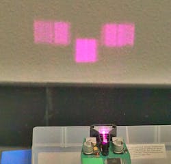
Lidar works like radar, as it is using ToF of the near Infrared light beams scattered out in front of the sensor. Since infrared is outside of the human’s visible spectrum, it’s hard to visualize what is taking place without the use of techniques that can help one see what’s happening in these wavelengths. Figure 3 shows a blended image I was able to acquire using special filters and camera techniques.
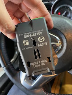
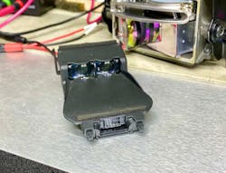
Essentially, the systems are attempting to produce a spatial 3-D point cloud to establish where any hazards may exist. Although wide use of lidar is currently not the norm, there are several vehicle manufacturers who have adopted some form of lidar on their vehicle. One popular sensor can be found on Mazdas, Toyotas, and Volvos (Figures 4 and 5) (I recently published a video detailing a live view of two different lidar sensors utilizing the Oculus which can be found here).
Limitations – ODD and OEDR
Today’s systems have numerous limitations, and as these systems evolve, their capabilities will improve. Service professionals should always refer to both the vehicle owner’s manual and service information before evaluating any complaints about system operation. The limitations may mirror the system complaint, which one would then need to review with the consumer. Just because one vehicle can respond to a road condition doesn’t mean all vehicles have the same capabilities.
Diagnostics and calibration
Many of the skills one needs for electrical and/or engine performance will serve well when addressing ADAS complaints and/or service requirements. If one wishes to gain a high level of competencies, then they should pursue training. Depending on the carline, you may have all the tools needed to address most diagnostic and service requirements.
Some vehicle manufacturers require special tooling such as static targets. Entering this market trying to become service-ready on every carline will be extremely challenging, but if you do your homework and find your addressable market, you’ll be on your way to creating a business plan. However, there are a few items you should be aware of.
The primary consideration is workspace. Some operations such as static camera/radar calibrations require a large amount of workspace with an extremely level floor. Additionally, when static camera calibrations are required, certain lighting conditions may present challenges. Reference service information for best practices around static camera calibration best practices. There are a number of aftermarket tooling solutions available. Personally, I have used the Autel Complete Solution (Red Frame w/cameras), the Bosch DAS3000, and others such as the John Bean EZ-ADAS. All three of these systems have focused on making the technician more productive without sacrificing accuracy. But beware, you should get in the habit of making sure that the target sizing aligns with what the manufacturer originally specified.
Case Study – 2021 Toyota Rav4
My shop had a client inquire about the behavior of their lane keeping system. Specifically, the lane tracing assist (LTA) system was allowing the vehicle’s right-side tires to cross over the right-side lane lines. When in the Lane Keep Assist (LKA) mode, the vehicle would warn the driver about approaching the left lane line about what one would expect, but for the right side, it was all happening well after the right-side tires passed over the lane lines. During the intake, we discovered the vehicle had recently had a replacement windshield installed, and this is when the symptoms surfaced. We commenced with analyzing the vehicle data by performing a complete health check, where there were no DTCs stored in any of the systems related to the complaints.
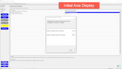
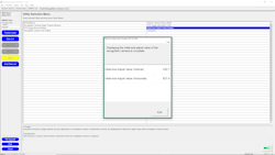
Using Toyota Techstream, we looked at the vehicle control history and could see that the vehicle recently had the camera calibrated, and the calibration process had completed. We then looked at the initial axis value that was recorded during that calibration and saved a copy (Figure 6). Looking at horizontal axis value had me concerned.
From my understanding, this is a pixel value used in establishing the baseline relationship to the imaging sensor with a known vehicle datum reference such as the vehicle centerline. The windshield mounted camera on this vehicle is vehicle centerline. I usually see these vehicles with that horizontal number in the ~630 range.
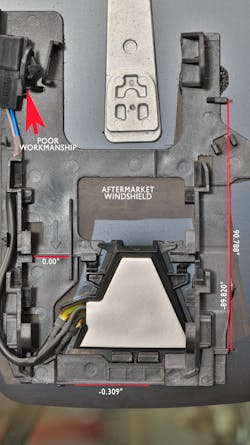
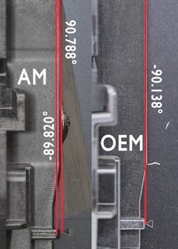
My next inspection was to look at the windshield branding. I found the windshield was from the same supplier as the OEM, but it was missing any of the OEM naming. I then decided to take a close look at the camera mount, which is glued in place to the windshield to see if there were any noticeable challenges, and this is when I decided we were going to recommend a factory windshield. Figure 7 shows the mount wasn’t properly indexed to the exact coordinates designated by the diamond shaped markers on the windshield.
If you look along the right side of the camera mounting bracket, you’ll see two vertical lines that were used to measure the angles after establishing the reference line at 0.000 degrees at the horizontal line indicated by the arrow on the left side of the bracket. Also, you can see where the camera heater had to be transferred from the old windshield, which still had part of the broken camera mount attached to the harness at the top left.
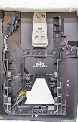
We received approval to install a new OEM windshield and when we received it, I took an image of it for comparison (Figure 8).
After installation and camera calibration utilizing our Autel Red-Frame system, we recorded the initial axis values using Toyota Techstream, which produced expected results (Figure 9). A thorough road test and performance analysis was performed on the LDW/LKA and found their operations well within the vehicle’s ODD. Figure 10 shows a side-by-side comparison of the two camera brackets.
The current state of DAS will eventually lead us to automated driving systems (ADS). The suite of sensors on any given vehicle can be impacted by service operations. It is in your best interest to gain a high level of situational awareness to ensure the vehicles passing through your service bays are receiving the proper care and attention the OEM intended to happen.
