Electronic controls: Lateral and longitudinal
Content brought to you by PTEN. To subscribe, click here.
Electronic controls have displaced many of the mechanical systems we once saw on vehicles years ago. Electronic throttle and steering are popular these days but we’re now seeing vehicles with systems such as electromechanical brake boosters, electric power steering executing lane changes, avoiding vulnerable road users (VRU), and more. This article will discuss service operations diagnostics surrounding these systems.
ADAS
Advanced driver assistance systems have been populating the vehicle beginning as far back as 2010, supporting SAE’s J3016 Level 0 vehicles which, for the most part, only offered visual and/or audible warnings to the vehicle operator when an unsafe condition was detected. Moving into higher levels (1 and 2) requires additional support via advanced electronic control systems supported by critical communication channels as shown in Figure 1. Technicians looking to stay ahead of the curve know that continuing education is an absolute must to stay service ready. Professional service providers possessing a deeper understanding on these systems will typically result in “less friction” for the service technician during diagnostics and service.
Throttle actuator control (TAC)
For more than two decades, electronic throttle bodies have been populating the vehicle market, and I suspect that you’ve seen more than a few with intermittent DTCs related to the throttle actuator. The device usually consists of a DC motor and two throttle position sensors that typically, but not always, output somewhat opposing signals, which are used to validate proper system operation. The DBW system took on a lot of heavy risk assessment study and had to pass through the Automotive Safety Integrity Level (ASIL) steps before standards for design and implementation could be approved. Generally, these systems have provided vehicle manufacturers additional tools that can be used to enhance vehicle performance, achieve emission compliance, minimize drivetrain wear, and maintain overall safe vehicle operation.
Troubleshooting
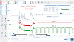
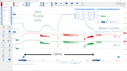
Service technicians dealing with intermittent faults on such systems should be aware that the safety engineers, as per safety requirements, are required to deploy a series of safety checks on the TAC systems before any propulsion torque commands can be issued to the vehicle. What this means is that upon key up or vehicle wake up, the system will run routines designed to validate the integrity of the system. The state of health checks may include RAM/ROM/EEPROM tests, analog-to-digital conversion tests, mechanical performance tests, shutdown tests, and so on. When a technician is dealing with a suspect throttle body, they may consider taking a deeper look at the throttle body using a digital storage oscilloscope (DSO), such as shown in Figure 2.
If you’re interested in seeing a self-test in operation, you can use their DSO to analyze this. Two channels can be used to log both throttle position sensors, and an amp current probe can be used on one of the motor circuits. The image shown in Figure 2 is from a 2004 GM V8 application, which was setting a P0120 (TP1 Circuit) and a P2135 (TP 1-2 Signal Correlation). The time shown between the cursors equals 486ms, which was captured at key up.
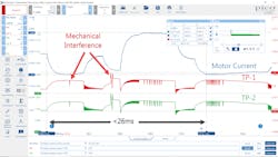
Figure 3 zooms in to the first 26ms of activity, where I observed what appeared to be a mechanical interference condition of the throttle plate, which was affecting both TP signals. The throttle body was extremely coked up with carbon and since it had over 200,000 miles on it, we recommended replacement over cleaning.
After replacement of the throttle body, I proceeded to collect a comparison DSO trace, so I could see what a new, known-good throttle body would look like during the same key-up self-test. Figure 4 shows a properly operating system.
I have collected dozens of images like this and have seen some that helped me to identify high commutator resistance on a brushed DC motor that I could not get to exhibit the symptoms described by the vehicle owner to appear while it was in the shop. However, the scope was able to provide me with some additional data points I then used to reinforce my recommendations for component replacement.
Braking systems
With the introduction of anti-lock braking (ABS), we’ve seen quite a few new pieces of hardware occupy the vehicle. Today, we’re seeing more and more alternative propulsion systems, such as hybrids and battery electric vehicles (BEVs) entering the fleet. With this new technology comes significant changes with the operational characteristics of the vehicle, often demanding other vehicle control methods.
Since hybrid and battery electric vehicles can take advantage of converting vehicle kinetic energy into electrical energy, additional engineering produced methods to reduce speed without much expense in brake wear. Therefore, you tend to see less brake wear on such vehicles if the vehicle is being operated properly.
On the internal combustion engine (ICE) side of the propulsion systems found on hybrids and extended range vehicles, engine vacuum was no longer abundantly available to supply the traditional power brake booster. This required either the addition of an electric vacuum pump or a complete redesign of the braking system. Looking back at the Toyota Prius, they relied on an electric pump to multiply the braking force applied to the brake pedal using a hydraulic pump and accumulator and in-turn, had to deploy a stroke simulator to provide the proper pedal feedback to the driver.
As the driver increases pedal force, elevated pressurized brake fluid is applied to all four-wheels programmatically (other manufacturers may deploy different methods for brake assist). When working on these systems, one should always follow the manufacture’s recommendations, so these electronically controlled systems are always ready to work at their full potential. Look for notices within the service information, so you can be sure to execute the proper relearning/recalibration steps prior to returning the vehicle back into operational status.
The following is a notification found within Toyota’s factory service information braking section after replacing the brake booster/master cylinder on a 2020 Prius:
NOTICE: After replacing the skid control ECU (brake booster with master cylinder assembly), perform linear solenoid valve offset learning, ABS holding solenoid valve learning, yaw rate, and acceleration sensor, zero-point calibration and system information memorization after performing "Reset Memory".
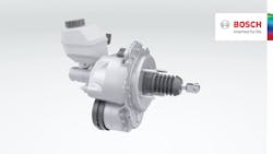
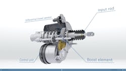
The Bosch iBooster (Figure 5) is a vacuum independent, electromechanical brake booster. Currently, there are two generations of the iBooster and is being used by multiple manufactures, including GM, Honda, Jaguar, Porsche, Tesla, and VAG vehicles. The unit can deliver varying brake pedal feel (selectable by the driver) and can greatly enhance the operational characteristics of hybrid/BEVs and offer even more assistance for vehicles equipped with certain ADAS features, such as adaptive cruise control (ACC) with stop-n-go support. The iBooster has an integrated control module and provides the power assist through its internal brushless DC motor, as shown in Figure 6.
Electric power steering (EPS)
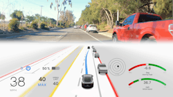
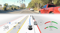
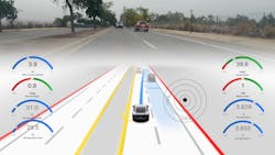
Although the first implementation of a full-control electric rack and pinion assist surfaced in 1990, this method wasn’t widely adopted until the early 2000’s. Again, the reason for moving to electric assist is because of the energy efficiency it brings to both ICE and BEVs, but it also allows more options, especially for those offering driver assistance features such as lane tracing/keeping assist (LTA/LKA) and active lane change assist (LCA) (Figure 7). EPS on some vehicles will nudge the vehicle back into the center of the lane when it determines that the vehicle is about to drive over clearly defined lane makings.
On some SAE J3016 Level 2 vehicles, automated lane changes can be achieved by the system. If you have driven a vehicle that can execute such a maneuver, I suspect that you admire the technology like I do. It is amazing to see a vehicle pull this off successfully.
Service and diagnostics
Although these systems may appear to be complicated, with the appropriate training, service information, and tooling, the service professional can work through any challenges presented. The key here in my opinion is to make sure that service personnel have an increased situational awareness of the service requirements of vehicles equipped with these systems. Services such as brake fluid replacement and wheel alignments aren’t so basic anymore, as these systems will likely require follow-up procedures to ensure the vehicle is operating to its full potential.
Additionally, it's important these vehicles are always operating with a sound electrical system and that starts with the 12V battery. Performing periodic battery inspections can go a long way toward preventing trouble from surfacing in these advanced systems. For the service technician tasked with performing diagnostics on any of these systems, a highly capable scan tool is essential during interrogation.
However, you may find that certain tasks may only be available using the OEM scan tool, and your mileage may vary. In other cases, you’ll likely need a DVOM, breakout leads, test probes, current probes, breakout boxes, a DSO, and possibly CAN tools when you’re up against something that falls outside of the diagnostic flow chart. See the case study featured in my article titled, "Vehicle network diagnostics: Today and the future."
The evolution of the automobile is not slowing down, and in fact, has accelerated quite a bit over the past five to eight years. Service professionals that keep up with these technologies are in high demand and will be highly valued for years to come in my professional opinion.
About the Author

Scott Brown
Founder - Diagnostic Network
Scott is an ASE Master Certified Automobile Technician with L1, L3, & L4 credentials and has over 39 years of professional service industry experience. As an independent shop owner in Southern California and with his engagement at various levels of within our industry, he continuously strives to move the industry forward through networking, education, communications, and training. Scott is a founder of the Diagnostic Network (https://diag.net/) which was born in 2018 after he retired after 22 years at iATN, where he served as company president.
Brown is also the host of Professional Tool and Equipment News (PTEN) and VehicleServicePros.com podcast, Torque Factor. The podcast addresses the latest automotive service technologies while focusing on expanding knowledge and awareness around tools, equipment, education, and industry trends.
