You've undoubtedly heard that tomorrow's fully autonomous vehicles will be able to accelerate, steer, and stop without ANY driver interaction. Vehicles with "drive-by-wire" however, are not just a future technology to simply be aware of. Drive-by-wire has been around for a few years. This month Motor Age will peek into the “new normal” of brake-by-wire systems.
Defining “Brake-by-Wire”
Anytime a vehicle’s brakes are applied without the driver’s foot doing the job can for all practical purposes, be referred to as brake-by-wire. Many examples can be found in today's vehicles;
· Traction Control Systems (positive wheel slip)
· Stability Control Systems (excessive yaw / lateral acceleration)
· Active Cornering Systems (a form of stability control – w/o loss of control)
· Auto Dry Braking Systems (applies brakes lightly and periodically in rain)
· Hill Start / Hill Hold
· ADAS;
o Adaptive (Radar) Cruise Control
o Collision Avoidance / Mitigation (frontal)
o Rear Automatic Emergency Braking (when backing up)
o Self-Parking
o Unattended self-steering systems (refuse to take the wheel while in some semi-autonomous models – the vehicle stops itself)
What Breaks in Brake-by-Wire Systems?
Key players for problems with any brake-by-wire system are;
· Functional WSS (Wheel Speed Sensors)
· Functional and properly calibrated ADAS radar sensors and cameras (if equipped)
· Fully Operational ABS Hydraulic Modulator Assemblies (a.k.a. Brake Actuator Assemblies)
· Brake fluid (ample level, proper type, and contamination free)
· Clean connections for 12-volt power, grounds and CAN data
Let’s look at the first those 1st two bullet points in more detail;
WSS (Wheel Speed Sensors)
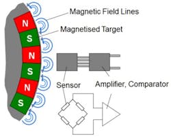
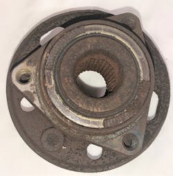
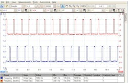
Wheel speed sensors have been around since the first days of ABS. Early ‘passive’ designs built on VR (variable reluctance) technology was sufficient in accuracy for its day but had problems resulting in poor ABS performance. For many years now, OEMs have been using ‘active’ MR style sensors which aren’t speed dependent and are more accurate. Diagnostics and common failure modes are different, however. (Figs. 1-3)
Proper ADAS Calibrations
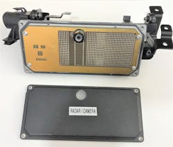
ADAS (Advanced Driver Assist Systems) sensors with problems can in some cases continue to operate but not at their fullest potential. While it is true that most sensors that are grossly miss-calibrated will set a DTC and driver alert, lesser degrees sensor offsets can create performance issues. For brake-by-wire collision avoidance/mitigation that could mean the vehicle's radar misinterpreting an approaching (or parked) vehicle in another lane as an impending collision with your customer's vehicle. The result on some occasions has been the customer’s vehicle ‘slamming’ on its brakes (without the driver’s brake apply). In other incidents, a few degrees of offset have led to the brake-by-wire systems (such as radar cruise control) not detecting the other vehicle your customer is approaching. If a driver depends on their brake-by-wire too much, these kinds of incidents can lead to a rear-end collision with another vehicle. Therefore, it’s important to learn all you can about ADAS even if you’ve elected to NOT purchase expensive static calibration equipment. Knowing when a static (in the shop adjustment with targets) and / or subsequent dynamic calibration (electronic adjustment during a road test) is essential. Sensor removal (to gain access to another component), wheel alignment, and windshield replacements are all potential lines in the sand for breaking out the ADAS calibration equipment or calling the diagnostic mobile tech with the correct calibration equipment and proper know-how. Brake-by-wire systems on ADAS equipped vehicles are typically activated during adaptive (radar) cruise control operation. This means the radar sensor in the grill would need to be properly calibrated if it were removed and replaced or its mounting bracket bent even slightly. What about the camera behind the windshield? On some ADAS vehicles, the grill mounted radar and windshield mounted camera (primarily for lane departure warning/lane keep assist) works in cooperation with each other. This means if you have a problem with the camera, the radar related systems might not perform properly and vice versa. In the case of some Volvo models, the long-range (millimeter) radar and 'smart' camera is integrated into the same assembly and mounted behind the rear-view mirror. (Fig. 4)
Understanding ADAS is the Key
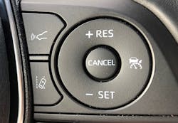
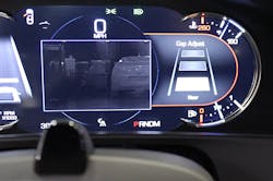
In addition to proper calibration, ADAS system operation MUST be understood. Since customers rarely educate themselves to the degree they should, this means you, the technician, service advisor, or repair shop owner needs to be your customer's technical trainer on ADAS. For example, on some earlier Toyota’s with adaptive cruise control systems the brake-by-wire system will only brake itself and slow the vehicle down to 20 MPH when the vehicle approaches another vehicle that is stopped. On later Toyota and Lexus models, the adaptive (radar) cruise control will bring the vehicle to a complete stop if the even a vehicle being followed stops. If your customer complains their adaptive cruise control doesn’t work, make sure they are not manually turning off their traction control. TRAC and VSV (stability controls) must be functional for their radar cruise to operate. Additionally, a thorough understanding of SWC (Steering Wheel Control) switches (Fig. 5) and instrument cluster displays for followed vehicle ‘gap’ adjustment (Fig. 6) are paramount for ensuring you are NOT being asked by your customer to “fix something that’s not broke!”
Integral ABS Returns . . . and Leaves Again
Antilock brakes (ABS) have been around for decades to give drivers more control of the steering while performing heavy braking. Probably the first form of brake-by-wire was TCS (Traction Control System) which added brake application to simple engine torque management. From the late 1980s into the mid-1990s, you may have noticed ABS systems taking two forms; integral and non-integral. Integral systems took a fresh design approach by completely changing the way the base brake hydraulics operated. Non-integral systems were simply “add on” ABS components to the traditional base brake hydraulics. With a typical non-integral ABS, the driver mechanically activates the two hydraulic brake circuits via the brake pedal/master cylinder to stop the vehicle. Now consider the typical integral ABS. Gone is the simple vacuum brake booster for power-assisted braking. Integral systems use an electric hydraulic pump along with a pressurized tank for their power assist feature. Instead of a brake actuator being located downstream from the master cylinder, (as with non-integral ABS systems) the master cylinder and ABS hydraulic modulator are built into a single “integrated” unit. You may have serviced these older integral ABS systems over the years. Bosch 2U, Teves Mark II, Delco Moraine (Delphi) III, etc. to name a few, were overly complicated “Rube Goldberg” designs by today’s standards.
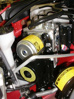
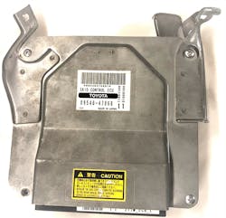
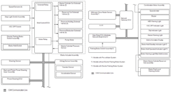
Eventually, non-integral ABS systems improved and began to overtake integral models. Improvements with the cheaper (and simpler) non-integral ABS system’s ability to “create brake pressure” w/o the driver’s foot pushing down the brake pedal had to occur for vehicles with these systems to work with traction and stability controls. Both TCS and stability controls require brake-by-wire activation. Just when we thought that those complicated and costly integral ABS systems were behind us, HEVs (Hybrid Electric Vehicles) and EVs (Electric Vehicles) began appearing with many similarities of the older complicated integral ABS systems. (Fig. 7) Toyota’s Gen II Prius (2004-2009) was a prime example of brake-by-wire complexity. When you applied the brake pedal, you were actually ‘requesting’ brake apply. A remotely mounted (buried under the dash) “Skid Control ECU” (Fig. 8) receives a “brake pedal stroke sensor” input as its cue to apply the brakes. Front friction brakes may not apply at all if the Skid Control ECU doesn’t see a panic stop indication. It communicates on the CAN bus with the Hybrid Control ECU. If the Hybrid Control ECU is fine with the need for regenerative braking (it almost always is) it then commands the inverter to place opposing forces on MG (Motor Generator) 2 to slow the front wheels based on the degree of braking the Skid Control ECU has advised it that you were applying with your foot on the brake pedal. This creates electricity which in turn charges the high voltage battery pack.
For panic stops, stops under 5 MPH and normal application of the non-driven rear brakes, the Skid Control ECU signals the ABS/brake actuator assembly to turn on the ABS pump, activate the correct solenoids and apply the brakes in a traction control system fashion. If a major problem with this brake-by-wire system is detected, the master cylinder's "cut valve" is activated for there to be a mechanical connection between the driver’s foot on the brake pedal and the hydraulic braking system. This back-up failsafe system from the cut valve doesn't employ any kind of power-assisted braking so don't assume your brakes are going to be easy to operate in this mode. I encountered a 2004 Prius that had a Skid Control ECU DTC. Braking power was nil to none. Apparently, the module couldn’t command the cut-valve to go into the proper failsafe mode. A used Skid Control ECU from an auto recycler for $65 saved me from the $1200 (wholesale) cost of a new one! You can read more about that case study in a previous Motor Age article back in June of 2012.
Newer Brake-by-Wire Vehicles
As non-integral ABS / TCS systems improved, brake-by-wire systems have become less mechanically complex. Their multi-system interactions, however, have increased in complexity exponentially. In the case of a new (2020) Camry (non-hybrid) with radar cruise, the remotely mounted “Skid Control ECU” is now integrated into the electronic module attached to the brake actuator (ABS) assembly. As with most of today’s ABS / TCS systems, this vehicle’s ABS brake actuator uses 12 solenoids and a pump motor to achieve whatever form of brake-by-wire the vehicle requests. (Fig. 9)
Checking Operation; Graphing Brake-by-Wire PIDs
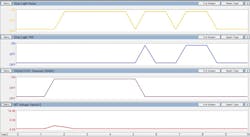
Graphing brake-by-wire scan tool Parameter IDs (PIDs) can be a benefit in diagnostics when you’re trying to go beyond simple DTCs to determine if the advanced braking systems such as TCS, stability controls and radar cruise is applying the friction brakes on your customer’s vehicle. Obviously, you can feel the harsher deceleration feel of friction brakes (compared to throttle down) while following another vehicle that applies its brakes when you’re in radar cruise mode. While that seat of the pants feeling is noticeable to your, documentation via a scan tool screen capture (Fig. 10) can add some tangible evidence that braking is occurring when the radar senses another vehicle in front slowing more rapidly than the cruise control’s throttle down can handle. A close look at Fig. 10 reveals what' going on when first the radar cruise, then the driver applies the vehicle's brakes. The top PID is the stoplight relay which turns on the stoplights when the friction brakes are applied by either the driver’s input to the brake switch or a brake-by-wire apply. The next row down is the PID for the stoplight switch on the brake pedal. The bottom PID (MT Voltage Value) is a bit of a mystery. Watching it during automated brake applications it never rose over 4.5 volts so one could conclude that the acronym “MT” might stand for “Motor Temp” Voltage Value. Regardless, this PID remained at 0-volts during non-braking as well as manual (pedal applied) braking occurrences. The 2nd from the bottom row PID is one of the TRAC / VSV (Traction Control / Stability Control) hydraulic solenoids in the brake actuator assembly. The bottom PID is the brake actuator’s pump motor. Observing from left to right, the stoplight relay turned on 3X (top PID graph) while the TRAC/VSV solenoid (2nd from bottom) turned on once. Notice the 2nd row from the top PID graph (Stop Light Switch) off during the first part of the recording. This proves the radar cruise interaction with the Skid Control ECU was braking the vehicle - not the driver. During the last half of the recording (right side of the graph) the stoplight switch status goes high (2nd row from top) at the same time as the brake light relay (top). Note the lack of TRAC/VSV actuation (bottom) during the right side of the graphs.
This proves the driver applied the brakes manually. One failure on some radar cruise / brake-by-wire vehicles is a brake light activation that occurs when the driver applies the brakes (easy to check in the shop) but NOT when the radar cruise applies the brakes. This would be a big safety issue during radar cruise use and very hard to diagnose (without another vehicle following you on a road test) if you did graph advanced braking scan tool PIDs as shown in this figure.
Some Reasons Adaptive (Radar) Cruise Control May Not Work (Courtesy Toyota)
· The forward recognition camera is temporarily unavailable
· The electric parking brake system is malfunctioning
· TRAC is turned off
· VSC is turned off
· Problem with stop light switch circuits
· Malfunction in the millimeter wave radar sensor assembly
· Beam axis of millimeter wave radar sensor assembly misaligned
· Millimeter wave radar sensor assembly becomes dirty
· Millimeter wave radar sensor assembly sensitivity reduced because of bad weather such as rain, fog, snow, or sandstorm
Considering Used ADAS Parts? You Might Think Twice!
According to the Toyota service manual, replacing the long-range (millimeter wave) radar sensor with a good used one from another vehicle can cause a mismatch of information between the two vehicles. On Toyota and Lexus models this may result in a C1A69 DTC in addition to an inoperative radar cruise feature. Looking at on-line prices for new radar sensors they appear to run between $400 and $2,000. Ouch! I’m guessing that’s also the “new normal” for the convenience and safety of brake-by-wire systems!
